Table of Contents
- Recap: Kubernetes Network Model
- Pod-to-Pod Communication on the Same Node
- Pod-to-Pod Communication Across Nodes
- Network Policies
- Services & DNS
- Service Mesh
- References
Recap: Kubernetes Network Model
Kubernetes enforces a flat, IP-per-pod network. The core principles are:- Unique Pod IP
Every Pod receives its own IP address. - Local Node Traffic
Pods on the same node communicate via localhost or the CNI bridge. - Cluster-wide Reachability
Pods on different nodes talk without NAT, thanks to the CNI (we’re using Cilium).
We use Cilium with eBPF for high-performance routing, policy enforcement, and load balancing—no IP masquerading required.

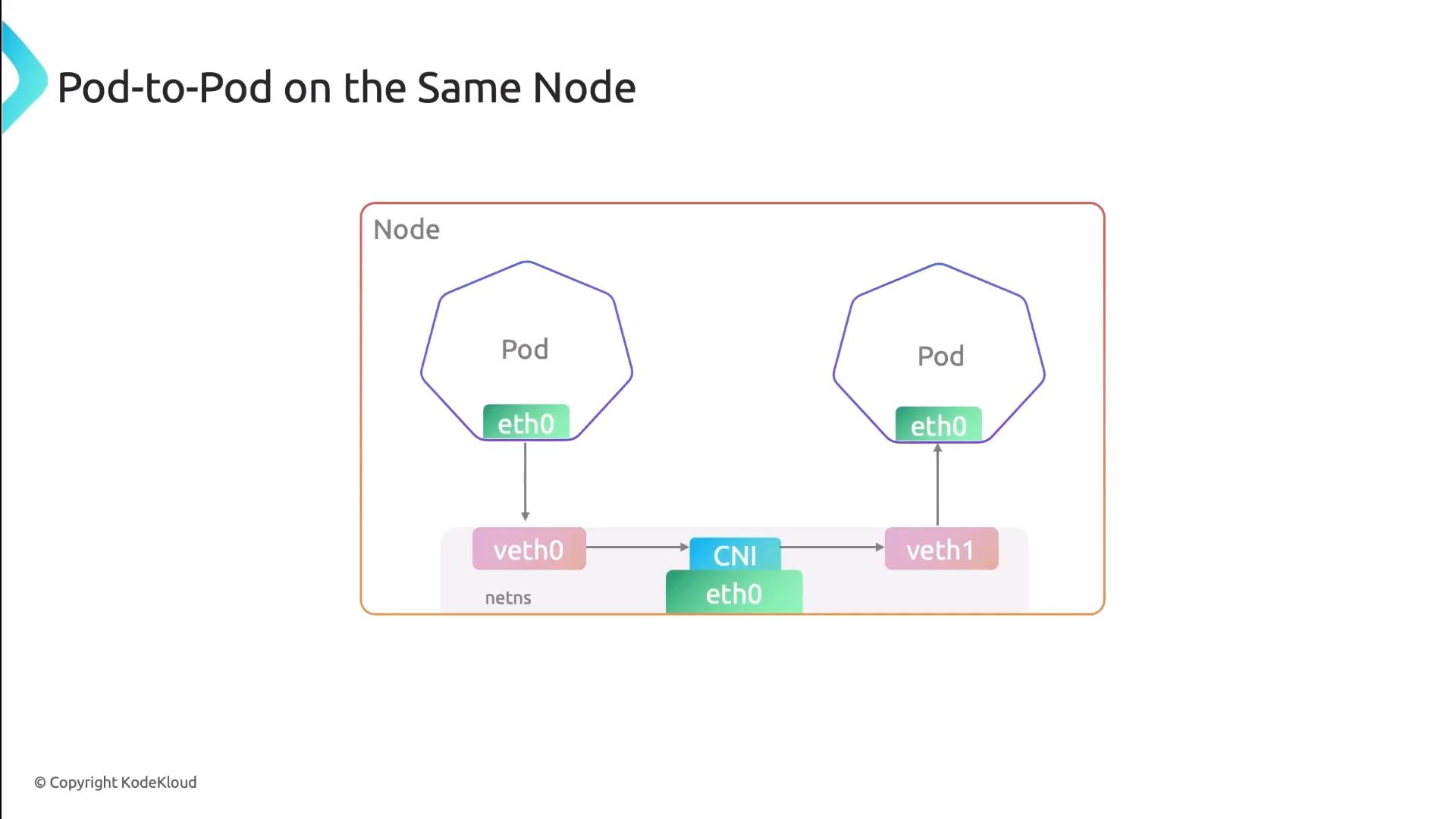
Pod-to-Pod Communication on the Same Node
When pods share a node, each pod’s network interface pairs with a veth endpoint on the CNI bridge. All traffic stays local:- Low latency, no encapsulation
- Direct IP routing on the bridge interface
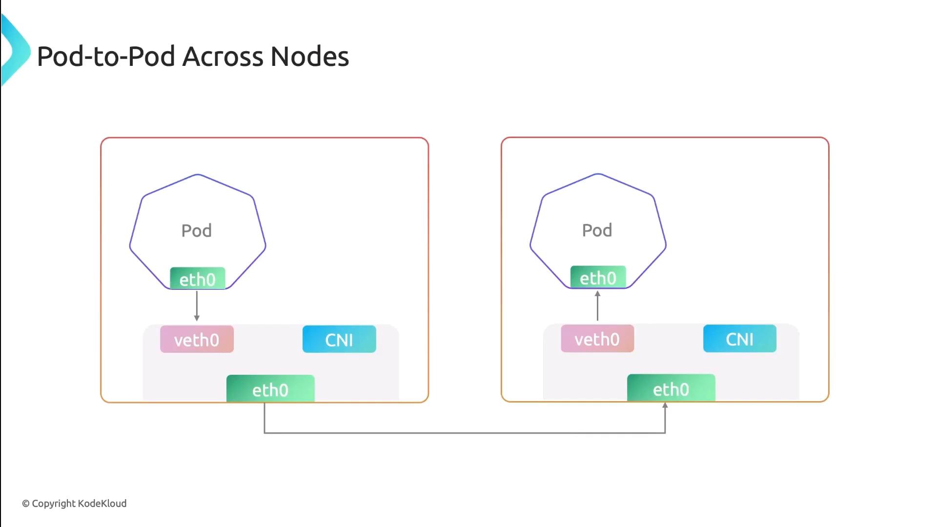
Pod-to-Pod Communication Across Nodes
For inter-node traffic, Cilium injects eBPF programs into the kernel to handle routing, encapsulation (if overlay is used), and policy. Traffic flows like this:- Pod → veth → Cilium eBPF hook
- Encapsulation (if enabled)
- Underlay network → remote node
- Decapsulation → destination pod
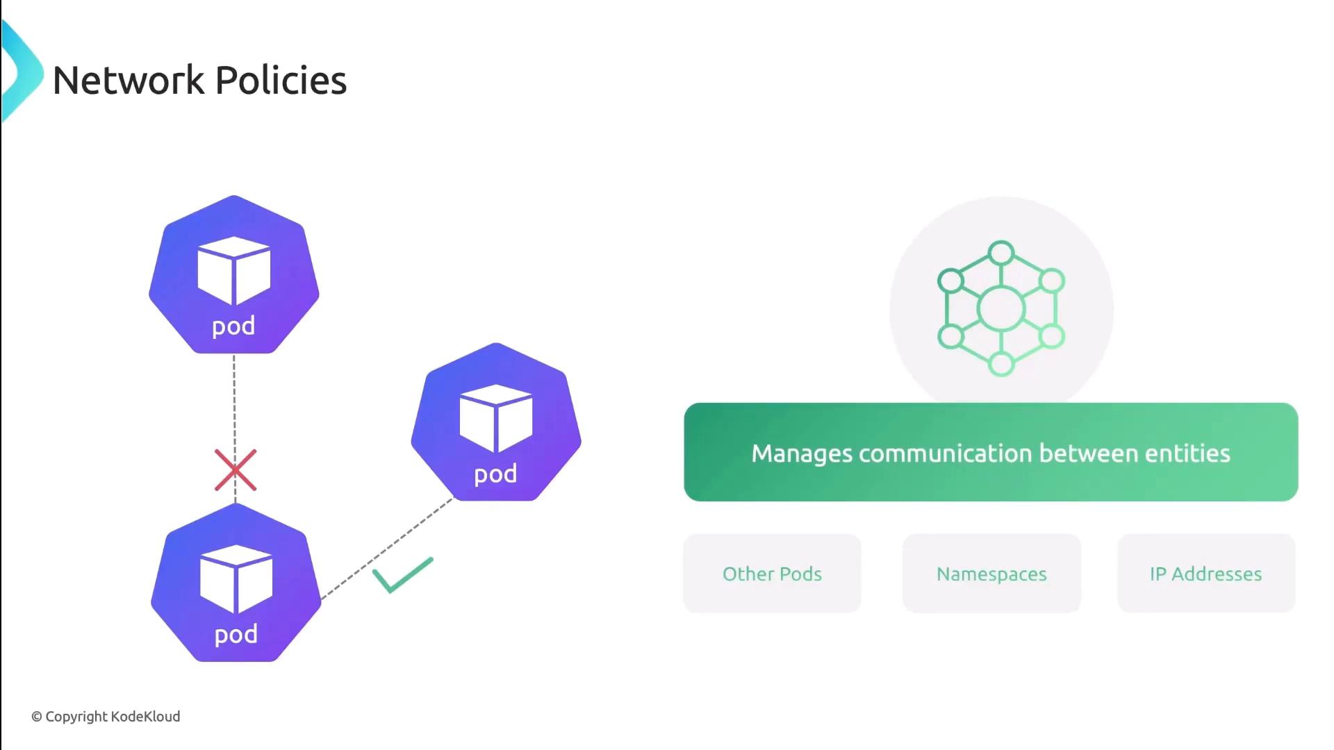
Network Policies
Network Policies control traffic at the IP and port level (TCP/UDP). You can specify which pods, namespaces, or external CIDRs are allowed or denied.| Feature | Description | Example |
|---|---|---|
| PodSelector | Select pods by label | podSelector: matchLabels: app: frontend |
| NamespaceSelector | Scope policy to namespaces | namespaceSelector: matchLabels: team:ops |
| IPBlock | Allow/Deny external CIDR ranges | ipBlock: cidr: 172.16.0.0/16 |
| PolicyTypes | Ingress, Egress, or both | policyTypes: ["Ingress","Egress"] |
Services & DNS
Kubernetes Services provide stable endpoints and built-in DNS discovery. Each Service gets a DNS A record, so clients always hit the right IP:- ClusterIP: Internal load-balancer
- NodePort: Exposes port on each node
- LoadBalancer: External cloud LB
| Service Type | Scope | Example Command |
|---|---|---|
| ClusterIP | Internal | kubectl expose pod nginx --port=80 --target-port=80 |
| NodePort | External | kubectl create service nodeport nginx --port=80 |
| LoadBalancer | Cloud LBs | kubectl apply -f loadbalancer-service.yaml |
Pod DNS records change on restart or rescheduling. Always prefer Service DNS names (
my-service.default.svc.cluster.local) for stable discovery.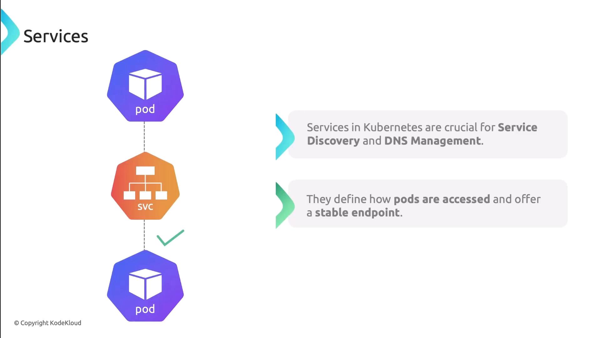
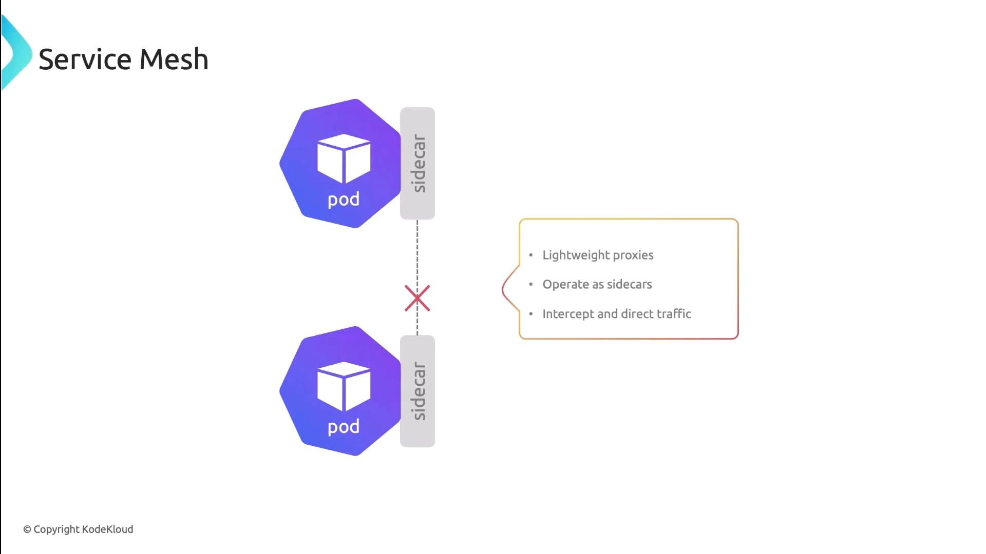
Service Mesh
A Service Mesh (e.g., Istio, Linkerd) injects sidecar proxies into each pod. These proxies manage:- Traffic routing and retries
- Mutual TLS (mTLS) encryption
- Circuit breaking and observability
In this lesson, we reviewed Kubernetes’ pod-to-pod connectivity patterns, network policies, Service DNS, and the power of a Service Mesh. Next, try applying these concepts in your own cluster!
References
- Kubernetes Networking Concepts
- Cilium Documentation
- Kubernetes Services
- Istio Service Mesh
- Linkerd Service Mesh