Microsoft Azure Security Technologies (AZ-500)

Perimeter Security

Implementing Azure Firewall

In this guide, we demonstrate how to implement Azure Firewall within a hub-spoke architecture. We cover the benefits and components of Azure Firewall—including Firewall Standard, Firewall Premium, and Azure Firewall Manager—and detail how to deploy it as part of your secure network design.

Azure Firewall requires a dedicated subnet, known as the Azure Firewall Subnet. Typically, you deploy this subnet within a central virtual network (the hub) and connect all other networks (the spokes) via VNet peering. By default, inbound internet traffic is denied; you can selectively allow traffic through specific firewall rules. Azure Firewall is also capable of inspecting on-premises traffic and routing it over a VPN gateway or ExpressRoute.

Below is a diagram illustrating this architecture:

The image illustrates an Azure Firewall implementation, showing a central virtual network (VNet) with an Azure Firewall Subnet connected to spoke networks A and B, managing internet traffic with rules and threat intelligence. Traffic is allowed or denied based on these rules, and there is connectivity to on-premises systems.

Overview of Deployment Steps

In this article, we will:

  • Deploy Azure Firewall in a central VNet (the hub)
  • Configure a new firewall policy that includes DNAT, network, and application rules
  • Create a dedicated subnet for Azure Firewall with an address space of at least /26
  • Provision a public IP address for the firewall
  • Deploy spoke virtual networks with Linux virtual machines using automation scripts to test connectivity
  • Set up VNet peering between the hub and the spokes

Let's start by deploying Azure Firewall through the Azure Portal.

Note

Ensure that you have the necessary privileges and a valid subscription before beginning the deployment process.

Deploying Azure Firewall in the Azure Portal

  1. Open the Azure Portal and search for “Firewall”. Click on Create.
  2. Create a new resource group (for example, RGFW).
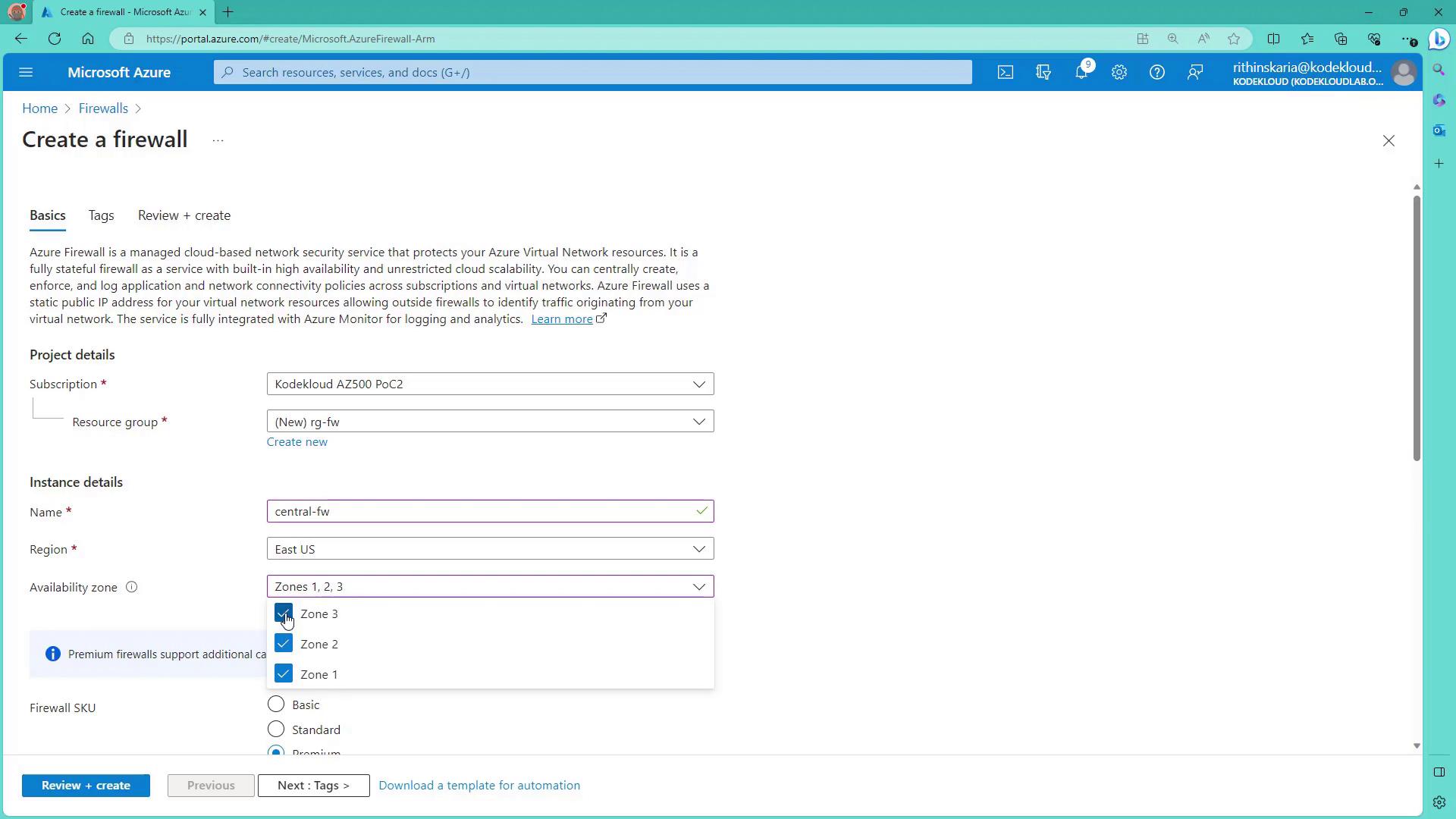
  3. Assign the firewall a name (e.g., Central FW) and select a region (e.g., East US). Optionally, enable availability zones if required.
  4. Choose the appropriate firewall SKU. Microsoft recommends using Standard or Premium for production environments. Premium includes advanced features such as SSL termination, IDPS, URL filtering, and web categories.
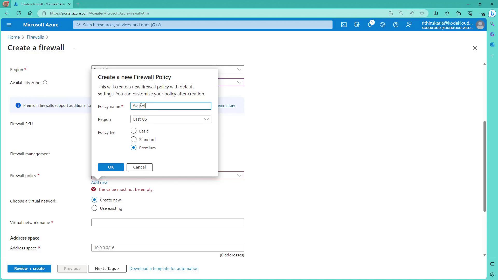
  5. Create a new firewall policy. This policy, a collection of rules (DNAT, network, and application), governs the flow of traffic through the firewall.

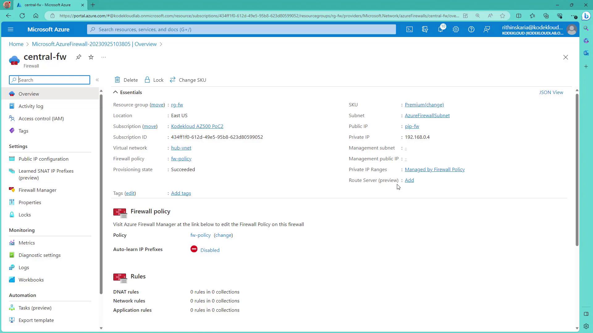
Configuring the Virtual Network

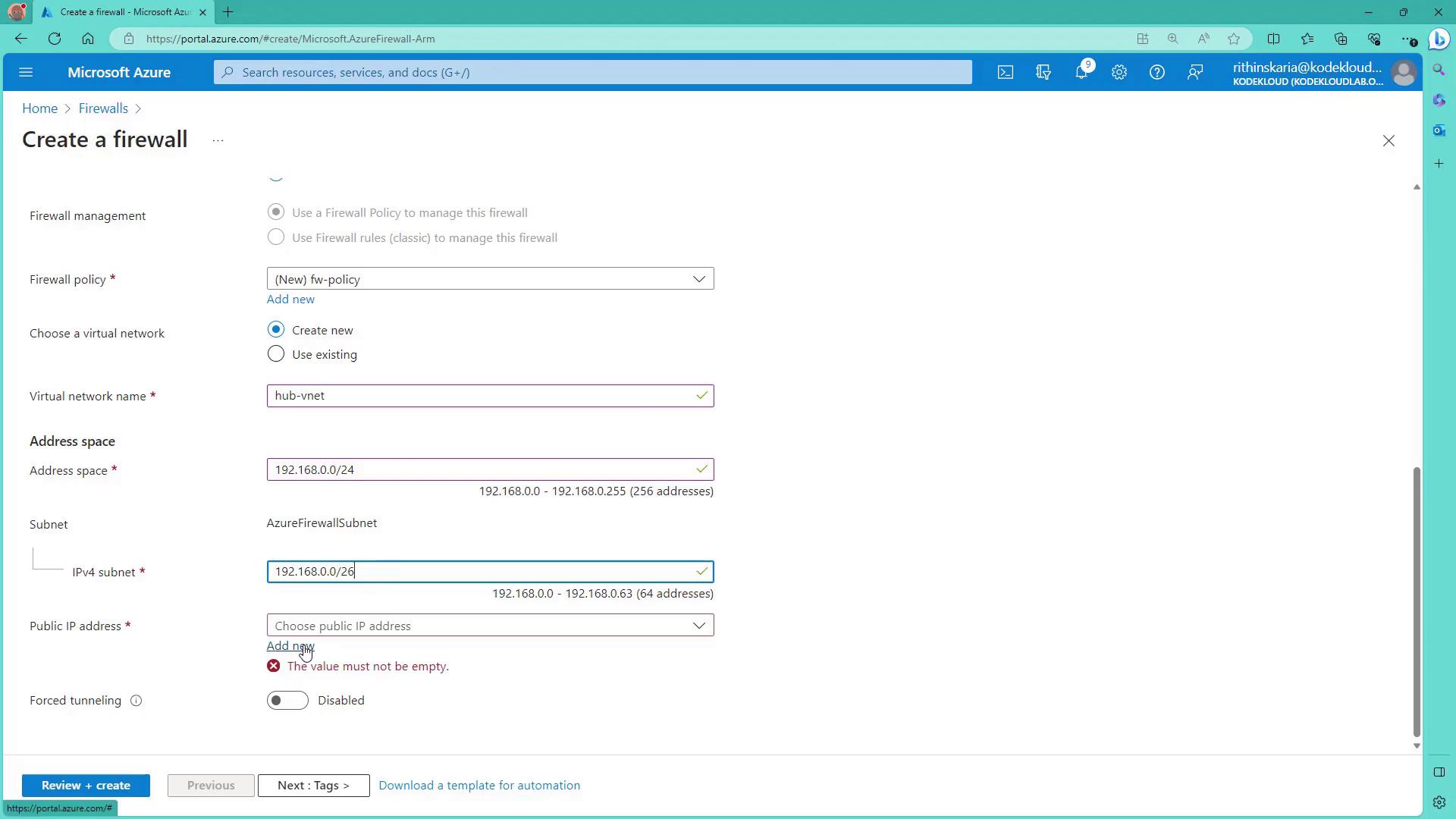
Select or create a virtual network for the firewall deployment. For example, create a new virtual network (Hub VNet) with an address space of 192.168.0.0/24. Within this virtual network, add a subnet for the Azure Firewall. The recommended subnet size is 192.168.0.0/26 (a /27 can be acceptable in some cases).

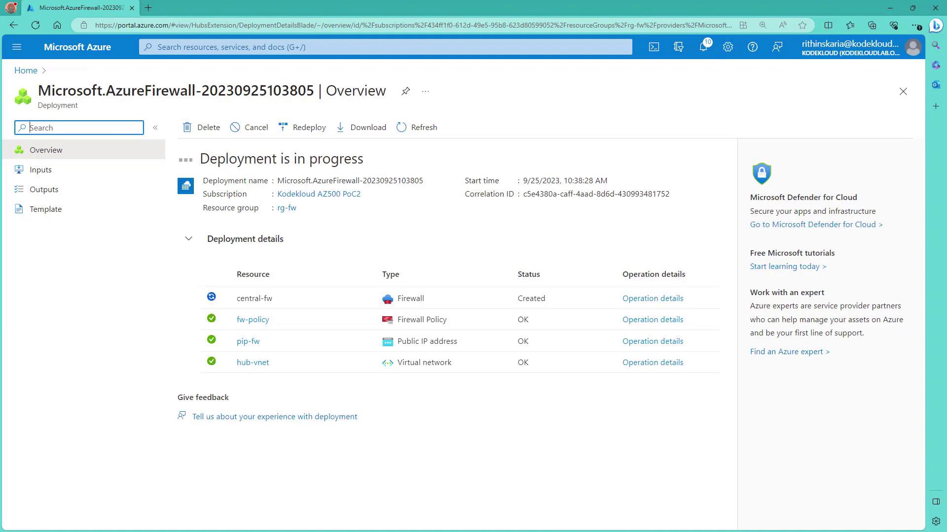
Next, assign a public IP address (for example, pipfw) to the firewall. For the present configuration, force tunneling remains disabled. Once tags are applied (if desired), click on Review and Create to deploy the firewall.

The following image shows the Azure Portal screen for creating a firewall with options such as subscription, resource group, name, region, and availability zones:

The image shows a Microsoft Azure portal page for creating a firewall, with options to configure project and instance details such as subscription, resource group, name, region, and availability zone.

After configuring the firewall, you will be prompted to create a firewall policy containing your DNAT, network, and application rules. Review the image below for an example of the firewall policy setup:

The image shows a Microsoft Azure portal interface for creating a new firewall, with a pop-up window for setting a new firewall policy, including options for policy name, region, and policy tier.

When configuring the virtual network details for the firewall, use the following settings:

  • Hub VNet Address Space: 192.168.0.0/24
  • Azure Firewall Subnet: 192.168.0.0/27 (or /26 as required)

After assigning the public IP address (pipfw) and completing the settings, the portal displays a configuration summary similar to the one below:

The image shows a Microsoft Azure portal page for creating a firewall, with options to configure firewall policy, virtual network, address space, and subnet settings.

Deploying Spoke Virtual Networks

Once the firewall is deployed, you can use scripts to create the spoke virtual networks. While manual creation is possible, using a script ensures consistency and saves time. The script will:

  • Create resource groups for the spokes
  • Set up the networking components
  • Configure Network Security Groups (NSGs)
  • Provision two Linux virtual machines per spoke

This script is available on GitHub under the "070 Perimeter Security" directory. Navigate to that directory and execute the script named firewall-prep-infra.ps1 to create the infrastructure.

Below is an example session output from running the script:

PS C:\Users\RithinSkaria\Documents\kodekloud-az560> cd '.\070~Perimeter Security\'
PS C:\Users\RithinSkaria\Documents\kodekloud-az560\070~Perimeter Security> .\firewall-prep-infra.ps1
Adding resource group : ng-fw-spoke-20230925
Adding spoke-a network configuration
WARNING: The names of some unapproved commands from the module 'Microsoft.Azure.PowerShell.Cmdlets.Network' include unapproved verbs that might make them less discoverable. To find the commands with unapproved verbs, run the Import-Module command again with the Verbose parameter. For a list of approved verbs, type Get-Verb.
Adding spoke-b network configuration
Setting up NSG to allow SSH traffic to VMs
Creating spoke-a-vm-1
spoke-a-vm-1 FQDN = spoke-a-vm-1.cf9bee.eastus.cloudapp.azure.com
Creating spoke-b-vm-1
spoke-b-vm-1 FQDN = spoke-b-vm-1.d13e8f.eastus.cloudapp.azure.com
Creating spoke-a-vm-2
spoke-a-vm-2 FQDN = spoke-a-vm-2.12387.eastus.cloudapp.azure.com
Creating spoke-b-vm-2
spoke-b-vm-2 FQDN = spoke-b-vm-2.e41572.eastus.cloudapp.azure.com
PS C:\Users\RithinSkaria\Documents\kodekloud-az560\070~Perimeter Security>

After the script completes, both the firewall and the Linux virtual machines will be deployed. The following image displays the deployment progress in the Azure Portal:

The image shows a Microsoft Azure portal page displaying the deployment progress of an Azure Firewall, with details about resources like firewall, policy, public IP address, and virtual network. The deployment status indicates that the firewall is created, and other resources are marked as OK.

Next, inspect the firewall resource within the Azure Portal. You'll notice that the firewall is managed through a firewall policy. Clicking on this policy reveals defined rules, including DNAT, network, and application rules. Review the central firewall overview in the image below:

The image shows the Microsoft Azure portal displaying the overview of a firewall named "central-fw," including its settings, policies, and rules.

Establishing VNet Peering

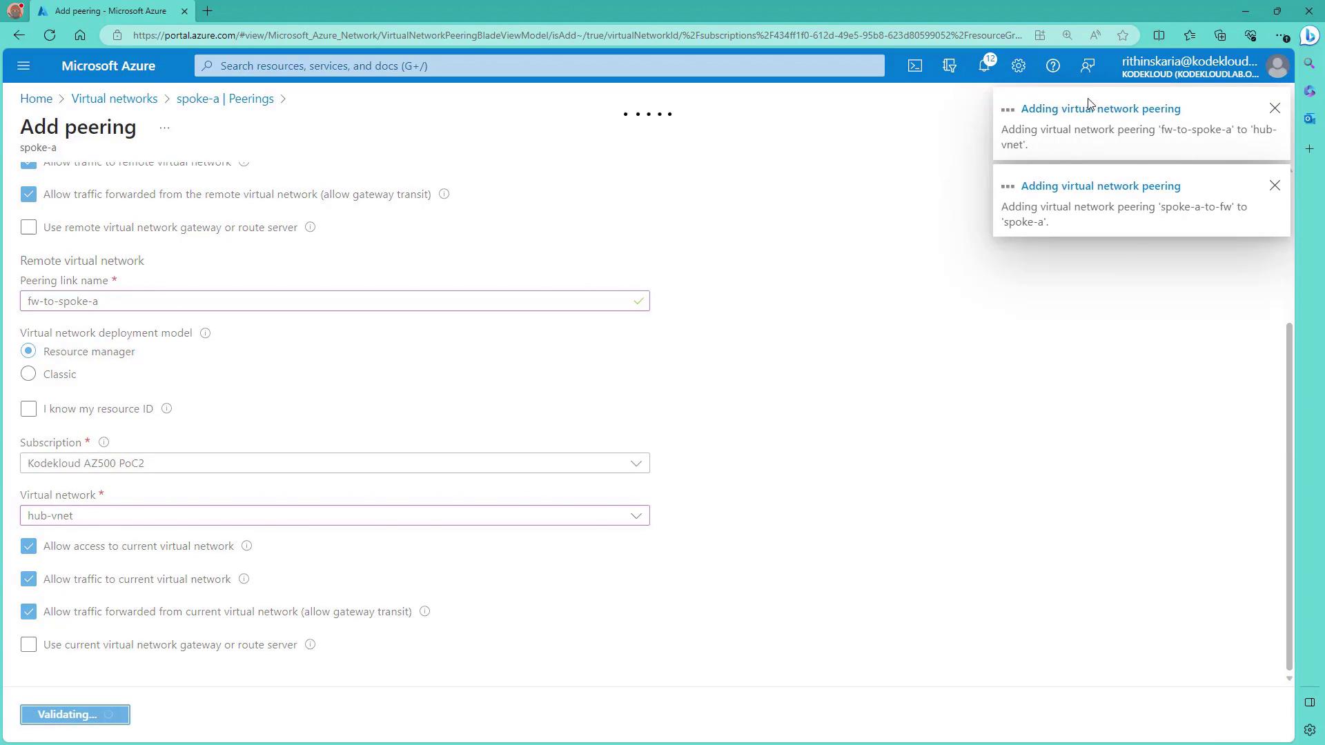
With Azure Firewall and the spoke networks in place, the next step is to enable VNet peering between the hub and the spokes.

Assuming that Spoke A and Spoke B have been deployed using the script, follow these steps:

  1. Navigate to Spoke A in the Azure Portal and select the Peering option.
  2. Click Add to create a peering connection from Spoke A to the Hub VNet (where the firewall is deployed). Ensure you enable settings such as "Allow access to remote network" and "Allow forwarded traffic" as needed.
  3. Name the peering connection appropriately (e.g., Spoke A to Firewall).
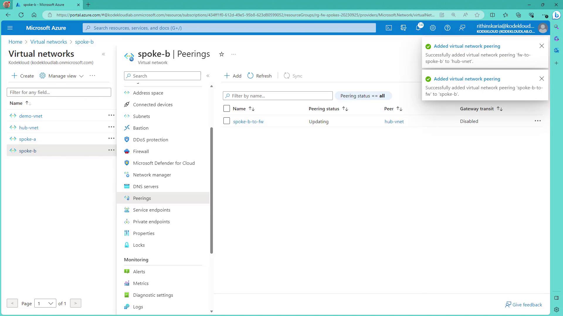
  4. Repeat the process for Spoke B, establishing a corresponding peering connection to the Hub VNet.

The next image demonstrates how to configure VNet peering:

The image shows a Microsoft Azure portal page for adding virtual network peering, with options to configure the peering link name, deployment model, subscription, and virtual network. Notifications about adding virtual network peering are visible on the right.

Warning

Gateway transit is typically not required unless routing traffic through a VPN gateway to on-premises networks. In this configuration, it is enabled for demonstration purposes only.

After configuring peering, verify the connection by checking the peering sections in each spoke network. The image below shows the successful addition of VNet peerings for Spoke B:

The image shows a Microsoft Azure portal interface displaying the "Peerings" section for a virtual network named "spoke-b." Notifications indicate successful addition of virtual network peerings.

Finalizing the Deployment

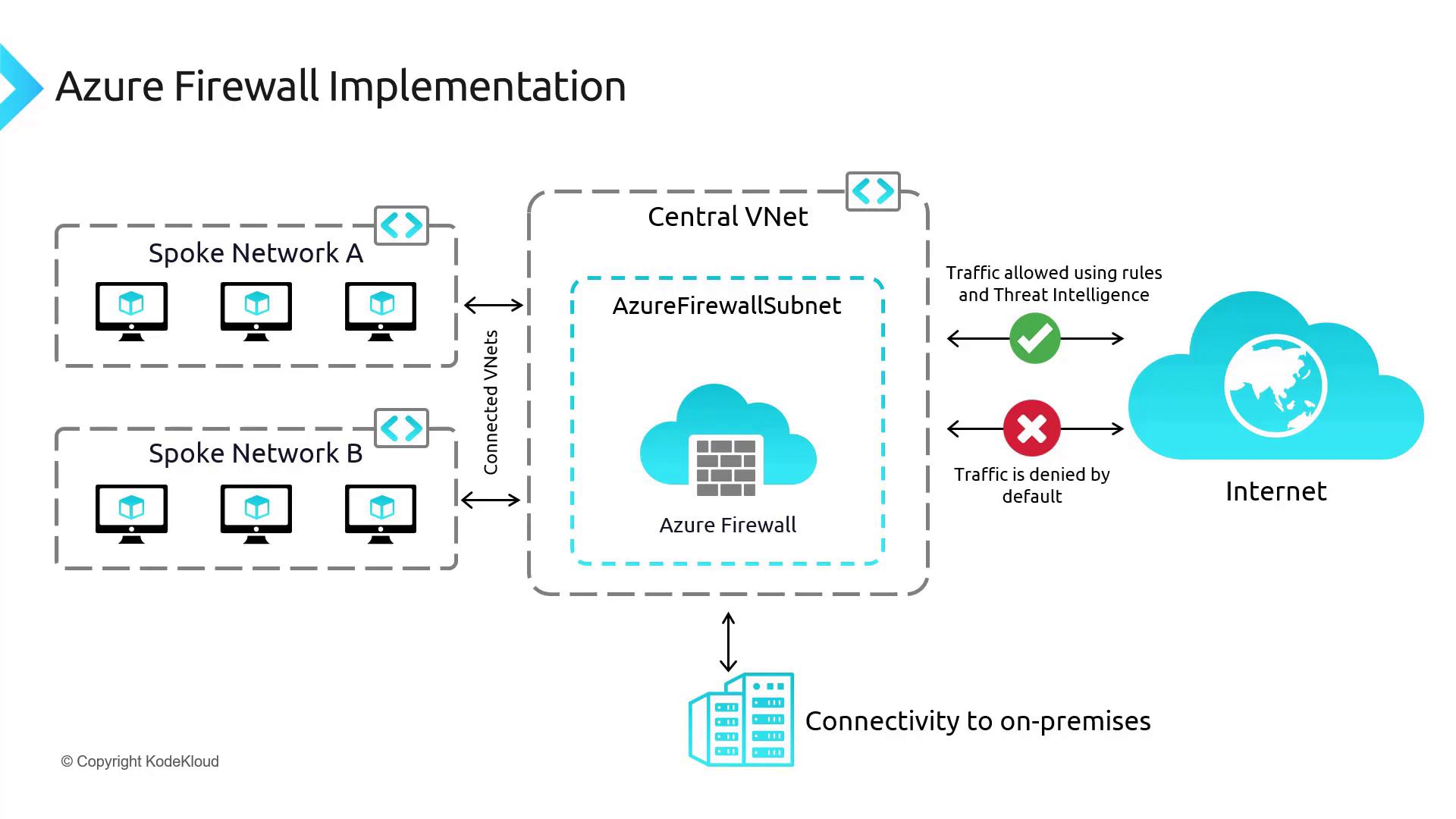
At this stage, all components of the architecture have been deployed. Note that traffic is not yet routed through the firewall. In upcoming lessons, we will configure User Defined Routes (UDRs) and refine the hub-spoke topology to direct traffic appropriately through the Azure Firewall. The following diagram illustrates the complete setup, including connectivity to on-premises systems—which will be addressed in detail later:
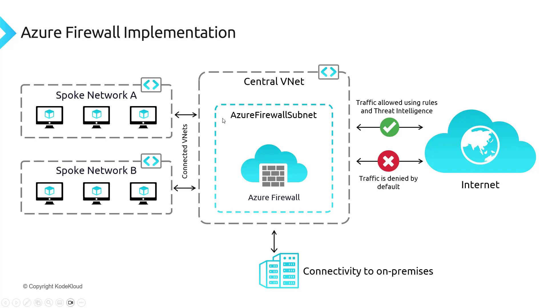
The image illustrates an Azure Firewall implementation, showing a central virtual network (VNet) with an Azure Firewall Subnet connected to spoke networks and the internet, highlighting traffic rules and connectivity to on-premises systems.

Summary

In this article, we have:

  • Deployed Azure Firewall in a central hub VNet.
  • Configured a firewall policy with various rule collections.
  • Created a dedicated subnet for the firewall and assigned a public IP address.
  • Used a script to deploy spoke virtual networks containing Linux VMs.
  • Established VNet peering between the hub and spoke networks.

While the deployment is now complete, further configuration (such as setting up UDRs) is required for full traffic routing through the Azure Firewall. Future lessons will cover these topics to ensure complete network security and functionality.

This concludes the discussion on implementing Azure Firewall.

Watch Video

Watch video content

Previous
Explore Azure Firewall features