When you provision an Azure Kubernetes Service (AKS) cluster, selecting the right network plugin is crucial for performance, security, and scalability. AKS supports two primary options:Documentation Index
Fetch the complete documentation index at: https://notes.kodekloud.com/llms.txt
Use this file to discover all available pages before exploring further.
- Kubenet (Basic): Uses separate address spaces for nodes and pods, with NAT and user-defined routes (UDRs).
- Azure CNI (Advanced): Integrates pods directly into your Azure Virtual Network (VNet), assigning them first-class IPs.
Kubenet Overview
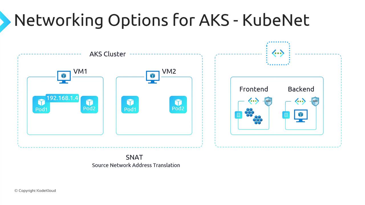
With Kubenet, AKS allocates node IPs from your VNet subnet and assigns pods to a secondary, logically distinct address space (by default a /24 per node). Outbound traffic from pods uses SNAT on the node IP, and inter-node pod traffic flows via UDRs you configure.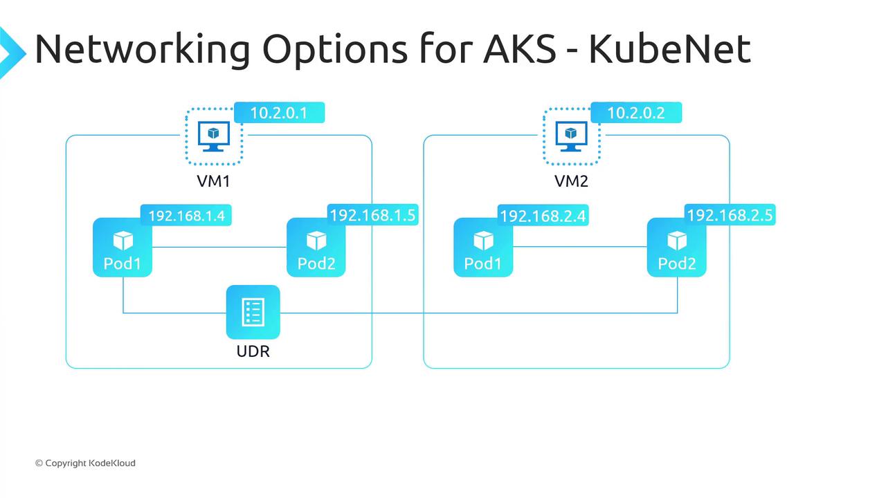
192.168.1.4 reaching a VM in another VNet (10.10.1.1) appears as the node’s IP and port to the destination.
Ensure your subnet and SNAT port allocation can handle peak pod-to-external flows. SNAT port exhaustion can disrupt outbound connectivity.
Azure CNI Overview
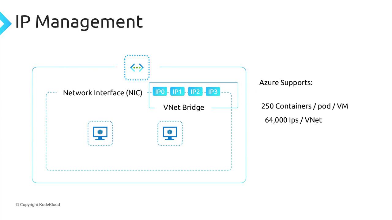
Azure CNI integrates directly into your Azure VNet, assigning both nodes and pods IPs from the same subnet. Pods become first-class citizens on the VNet, enabling native routing to other Azure services, on-premises systems, and peered VNets (subject to NSGs/UDRs).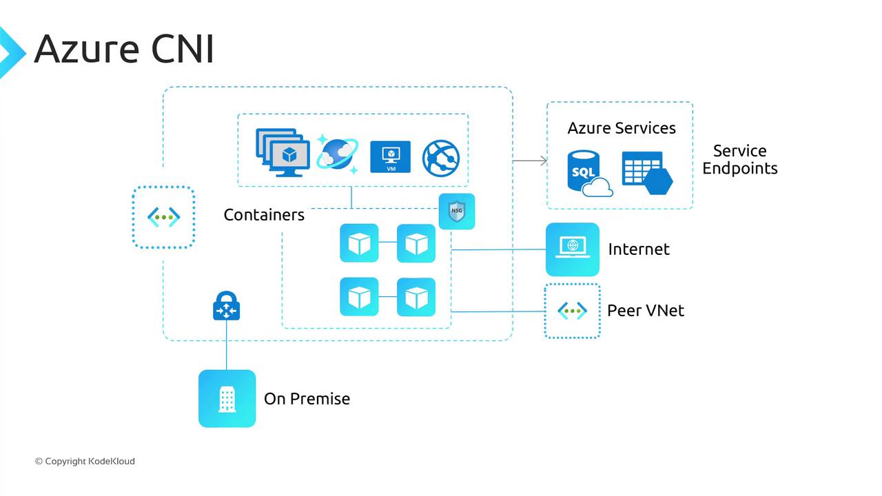
- Native IPs for pods—no SNAT for intra-VNet traffic.
- Automatic NSG/UDR enforcement on pod interfaces.
- Compatibility with Ingress controllers, DNS, Kubernetes Network Policies, and Windows Server node pools.
Plan VNet size carefully: Azure CNI consumes one IP per pod. A /24 supports up to 250 pods per node, so allocate your address space accordingly.
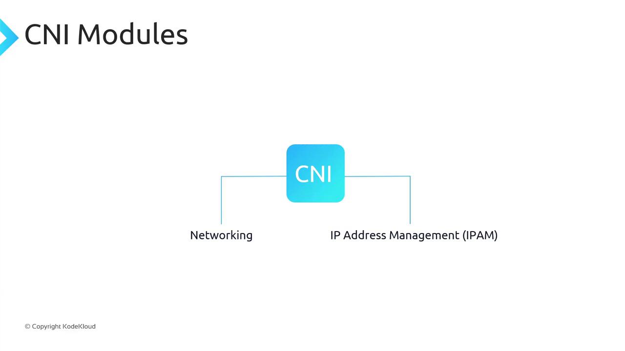
How Azure CNI Works
Azure CNI implements the CNI spec with two modules:- Networking: Attaches a virtual network interface (vNIC) to each container.
- IP Address Management (IPAM): Allocates/deallocates IPs from the subnet pool.
Comparing Kubenet and Azure CNI
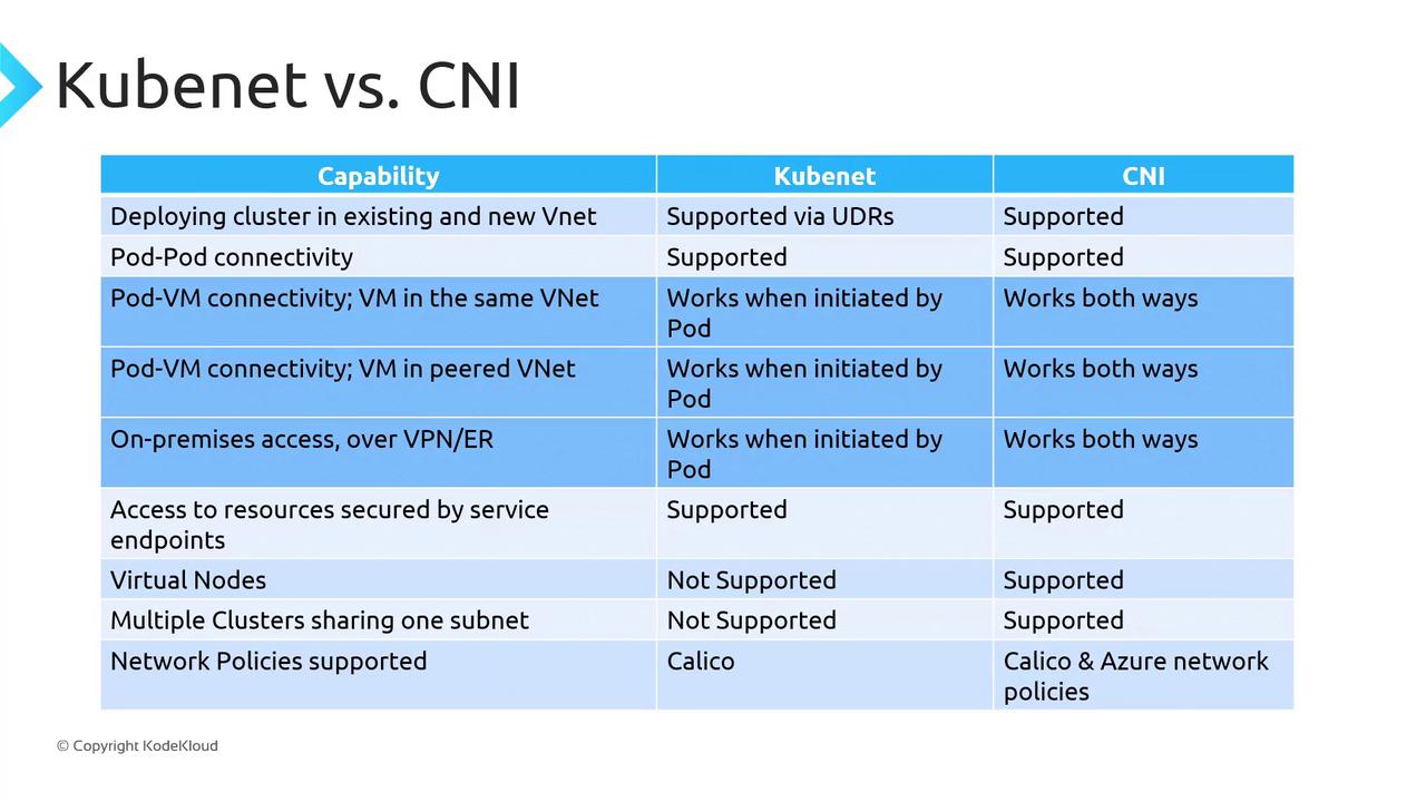
| Feature | Kubenet | Azure CNI |
|---|---|---|
| Pod IP allocation | Secondary network (/24 per node) | First-class VNet IP |
| Outbound NAT | SNAT on node IP | No SNAT for VNet traffic |
| NSG & UDR enforcement | Nodes only | Pods and nodes |
| Max pods per node | Limited by secondary CIDR (/24 ≈ 250 pods) | Up to 250 pods per node |
| Windows Server node pools | Supported | Supported (only CNI option) |
| Virtual nodes | Not supported | Supported |
When to Use Each Plugin
| Use Case | Recommended Plugin |
|---|---|
| Limited VNet address space | Kubenet |
| No need for pod inbound connectivity | Kubenet |
| Can tolerate SNAT overhead | Kubenet |
| Pods require direct VNet routing | Azure CNI |
| Advanced Azure Network Policies | Azure CNI |
| Virtual nodes or Windows pools | Azure CNI |
Links and References
- Kubernetes CNI Plugins
- AKS Networking Documentation
- Azure Virtual Network
- Container Networking Interface (CNI) Spec