This article explains pod networking in Kubernetes, covering implementation, inter-pod communication, and the role of CNI in managing network interfaces.
Welcome to this deep dive into pod networking in Kubernetes. In this article, we explain how pod networking is implemented within a Kubernetes cluster, detailing the steps that make inter-pod communication seamless across multiple nodes.Kubernetes clusters consist of multiple master and worker nodes with pre-configured networking that allows full node-to-node communication. We assume that all Kubernetes control plane components (e.g., kube-apiserver, etcd, and kubelet) are already set up properly. With this foundation in place, the next step is deploying your applications with a focus on robust pod-level networking.
Each pod gets a unique IP address.
Every pod on a node can reach every other pod on that node using its IP address.
Pods across different nodes can communicate using a consistent addressing scheme.
These requirements ensure that Kubernetes can support both local (node-level) and cross-node communications without relying on NAT rules.
Before deploying applications, it is crucial to address several questions:
How are pods assigned IP addresses?
How do these pods communicate both within a node and across nodes?
How can services running in these pods be accessed from inside or outside the cluster?
Kubernetes leaves the implementation details for pod networking to the user, as long as the chosen solution meets the basic connectivity requirements. Many networking solutions are available; here, we demonstrate the core concepts using Linux network namespaces, bridge networks, and IP address management inspired by CNI concepts.
Below is an example that sets up a simple bridge network and connects network namespaces:
Copy
ip link add v-net-0 type bridgeip link set dev v-net-0 upip addr add 192.168.15.5/24 dev v-net-0ip link add veth-red type veth peer name veth-red-brip link set veth-red netns redip -n red addr add 192.168.15.1 dev veth-redip -n red link set veth-red upip link set veth-red-br master v-net-0ip netns exec blue ip route add 192.168.1.0/24 via 192.168.15.5iptables -t nat -A POSTROUTING -s 192.168.15.0/24 -j MASQUERADE
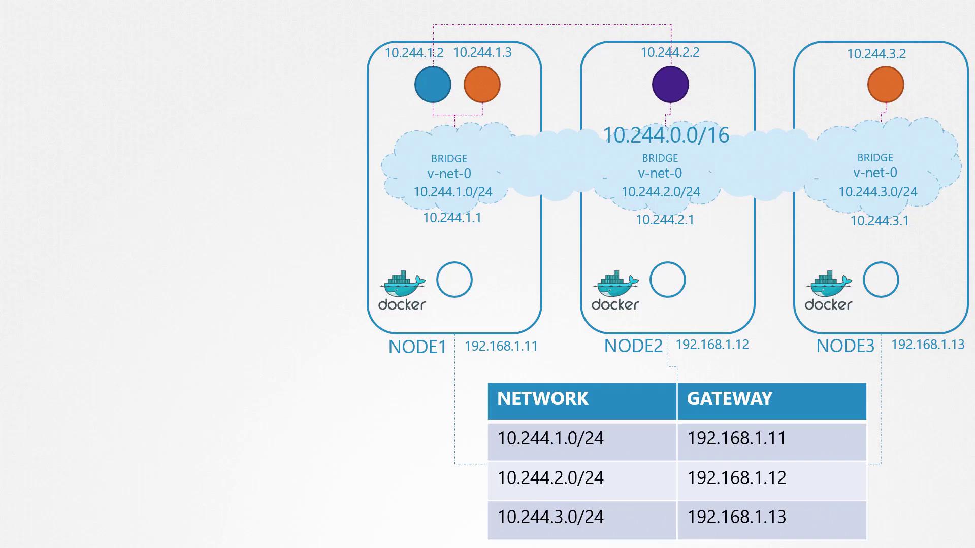
Imagine a cluster with three nodes where every node runs a combination of management and workload pods. Although node roles are flexible, the networking concepts remain consistent across nodes.
Consider the following plan for a three-node cluster:
External Network Configuration: Each node has an IP in the 192.168.1.0 series (e.g., 192.168.1.11, 192.168.1.12, and 192.168.1.13).
Container Network Namespaces: Kubernetes creates unique network namespaces when containers start. These namespaces must connect to a network to allow inter-container communication.
Bridge Networks on Each Node: Create a bridge network on every node. Assign a distinct subnet to each bridge, such as:
Node one: 10.244.1.0/24
Node two: 10.244.2.0/24
Node three: 10.244.3.0/24
When a container is created, a virtual cable (veth pair) connects its network namespace to the node’s bridge network. One end is inserted into the container’s namespace and the other attaches to the node’s bridge. An IP address is assigned (for example, 10.244.1.2), and a route to the default gateway is configured before enabling the interface.Below is a sample snippet from a script that connects a container to the network:
Copy
# Create veth pairip link add <veth-in-host> type veth peer name <veth-in-namespace># Attach one end to the container’s namespaceip link set <veth-in-namespace> netns <namespace># Attach the other end to the bridgeip link set <veth-in-host> master <bridge># Assign IP address to the container’s interfaceip -n <namespace> addr add <IP-address>/24 dev <veth-in-namespace># Add default route in the container’s namespaceip -n <namespace> route add default via <bridge-IP># Bring up the container’s interfaceip -n <namespace> link set <veth-in-namespace> up
Executing this script on each node ensures that all containers receive an IP address and are connected to their respective internal networks.
One of the challenges is enabling communication between pods on different nodes. For example, if a pod with IP 10.244.1.2 on node 1 attempts to ping a pod with IP 10.244.2.2 on node 2, the ping may initially fail due to unknown routes between subnets:
Copy
bluepod$ ping 10.244.2.2Connect: Network is unreachable
To resolve this, add a route on node 1 that directs traffic for 10.244.2.2 via node 2’s external IP (e.g., 192.168.1.12):
Copy
node1$ ip route add 10.244.2.2 via 192.168.1.12
After configuring the routing, the ping command should succeed:
Copy
bluepod$ ping 10.244.2.264 bytes from 10.244.2.2: icmp_seq=1 ttl=63 time=0.587 ms64 bytes from 10.244.2.2: icmp_seq=2 ttl=63 time=0.466 ms
Similarly, add these routes on all nodes to cover all pod subnets:
Copy
node1$ ip route add 10.244.2.2 via 192.168.1.12node1$ ip route add 10.244.3.2 via 192.168.1.13node2$ ip route add 10.244.1.2 via 192.168.1.11node2$ ip route add 10.244.3.2 via 192.168.1.13node3$ ip route add 10.244.1.2 via 192.168.1.11node3$ ip route add 10.244.2.2 via 192.168.1.12
Manually configuring routes on every host is impractical for large-scale deployments. A more scalable solution involves configuring a centralized router to manage all subnet routes and setting each node’s default gateway to this router.
Below is an image that illustrates a Docker network setup with three nodes, each with distinct IP addresses and subnet configurations, connected via a virtual network bridge:
In our lab setup, we executed scripts manually to configure pod networking. However, in a production Kubernetes environment where thousands of pods may be created per minute, this manual approach is not feasible.This is where the Container Network Interface (CNI) becomes essential. CNI specifies how Kubernetes should invoke a networking script each time a pod is created. To conform with CNI standards, the networking script must have:
An “add” section to connect the container to the network.
A “delete” section to disconnect the container, remove interfaces, and free up the IP address.
When the container runtime launches a container, it uses the CNI configuration (provided as a command-line argument) to execute the relevant script with the command “add” and pass the container’s name and namespace identifier.Below is an example snippet that illustrates the CNI execution process:
Copy
ip -n <namespace> link set <interface> upip link del <interface>./net-script.sh add <container> <namespace>
In this article, we covered the essential concepts behind pod networking in Kubernetes—from manual network namespace and bridge configuration to the role of CNI in automating network interface management. The techniques discussed here lay a solid foundation for understanding and troubleshooting pod networking in a Kubernetes cluster.Stay tuned for upcoming articles where we integrate detailed CNI configurations into Kubernetes workflows and provide practical tests to reinforce your learning.For more insight into Kubernetes networking, visit the Kubernetes Documentation.