- Frontend: The entry point for incoming requests (the load balancer itself, not your application).
- Backend: The pool where your application servers reside.
- Load Balancing Rules: These rules define how traffic is routed from the frontend to the backend.
Azure Load Balancer SKUs
Basic SKU
The Basic Load Balancer is ideal for development and testing environments due to its simplicity and cost-effectiveness. Key characteristics include:- Basic load balancing capabilities
- Operates within an availability set in the same data center
- Supports up to 300 instances
- TCP and HTTP health probe support
- Optional integration with Network Security Groups (NSGs)
- No redundancy and lacks an SLA guarantee
Standard SKU
Designed for production workloads, the Standard Load Balancer provides advanced features and higher performance:- Availability zones and cross-region load balancing support
- Microsoft peering for enterprise-grade applications
- Scale support for up to 1000 instances
- Enhanced diagnostic features, including HA ports and TCP reset
- Strict NSG enforcement for improved security
- 99.99% SLA for production environments
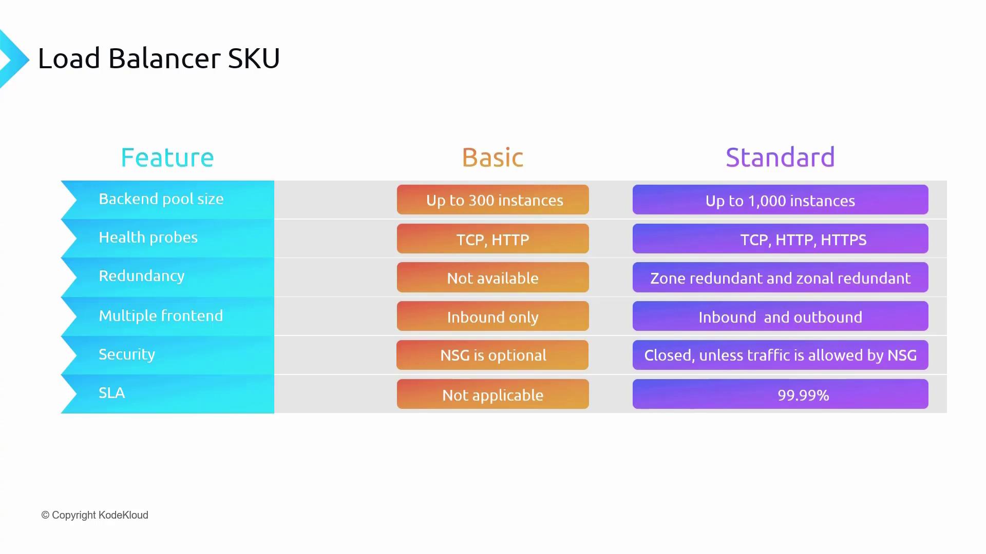
For non-critical development or testing workloads, the Basic SKU may be sufficient. However, for production deployments requiring scalability and enhanced reliability, the Standard SKU is recommended.
Load Balancer Types: Public and Internal
Public Load Balancer
For scenarios such as hosting a static website in a virtual network’s web subnet, a Public Load Balancer is used. It features a frontend with a public IP address, enabling end users to access your website on port 80 via the DNS name or public IP address. The following diagram illustrates a typical Public Load Balancer setup: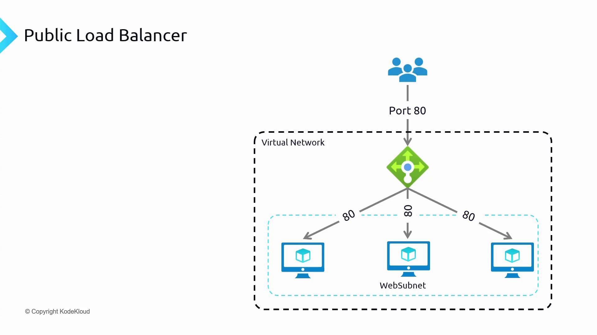
Internal Load Balancer
An Internal Load Balancer is best suited for distributing traffic among servers that handle internal workloads. For example, if you have a backend database that should not be exposed to the internet, an Internal Load Balancer (without a public IP) can distribute traffic securely among your database servers.Deploying the Infrastructure
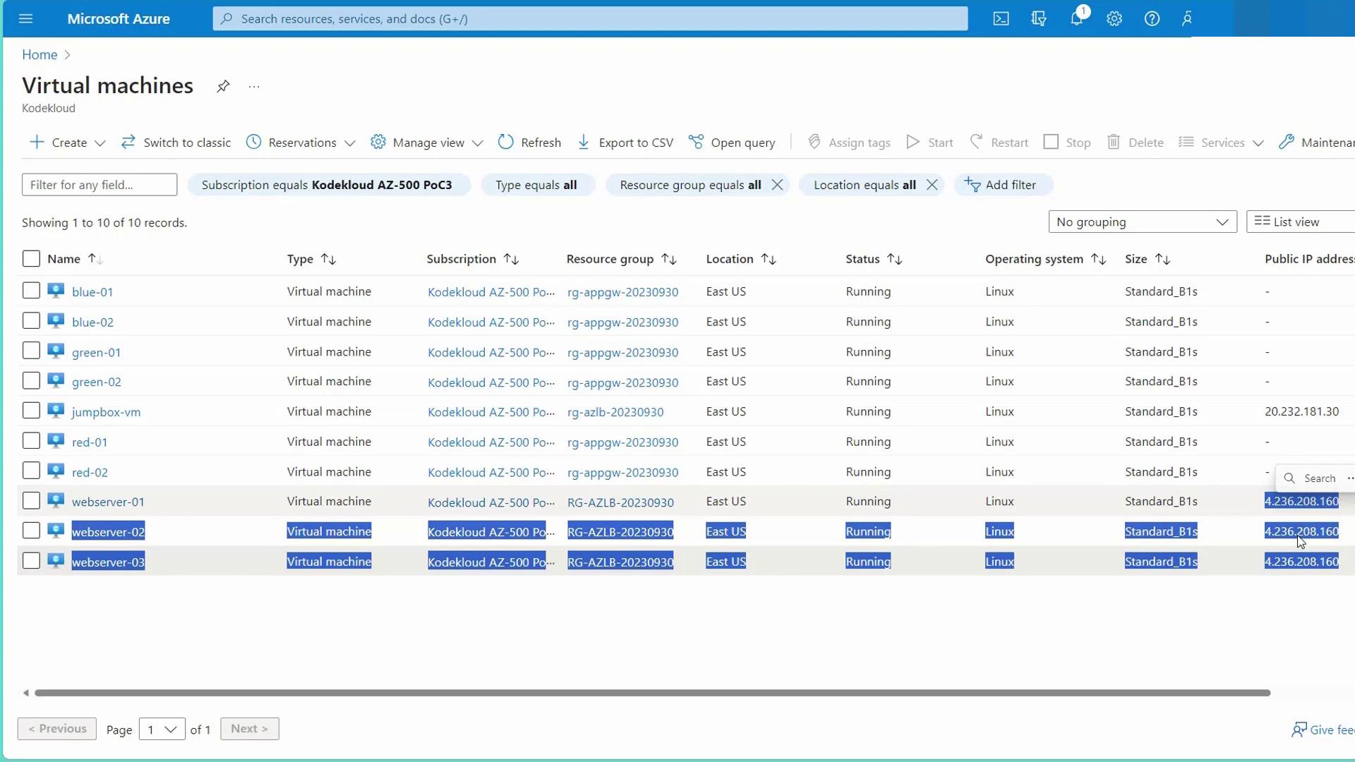
Before configuring the load balancer, deploy the required infrastructure using the “ACLB Prep Infra” script. This script creates necessary resources including:- Three web servers deployed within an availability set
- A jump server for management access
Configuring the Public Load Balancer
Follow these steps to configure a standard public-facing load balancer via the Azure Portal:-
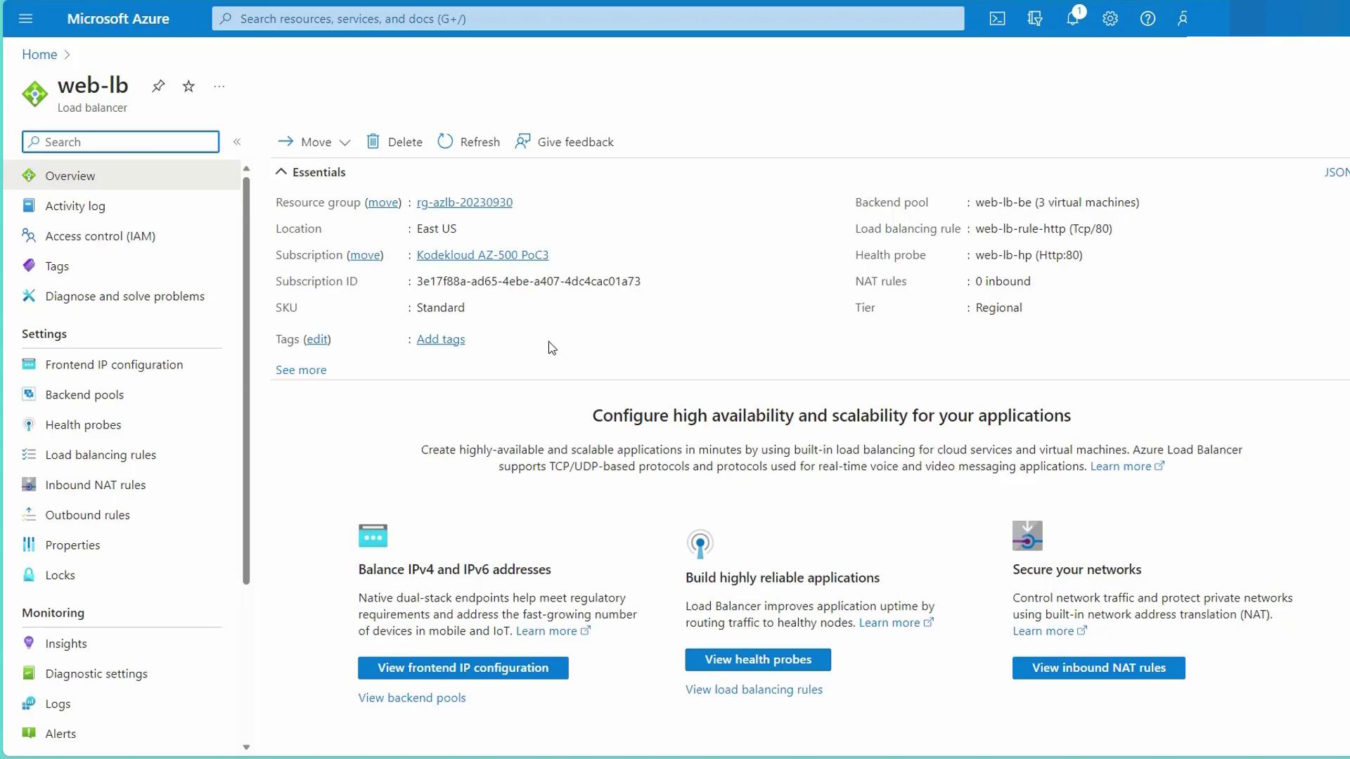
Create the Load Balancer:
- Select the region (e.g., East US) and set the SKU to Standard.
- Choose “Public” as the type and “Regional” for the deployment model.
-
Configure the Frontend IP:
- Create a new public IP address (e.g., “web LB PIP”).
- This public IP will serve as the entry point for the load balancer.
-
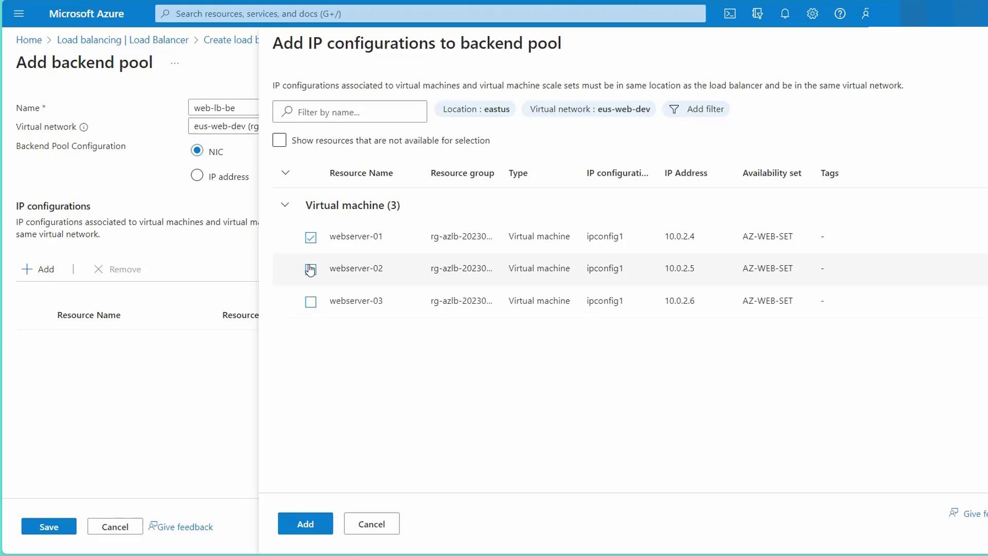
Configure the Backend Pool:
- Establish a backend pool by adding all web servers from the “US Web Dev” availability set.
- Verify that all the web servers are included in the backend pool.
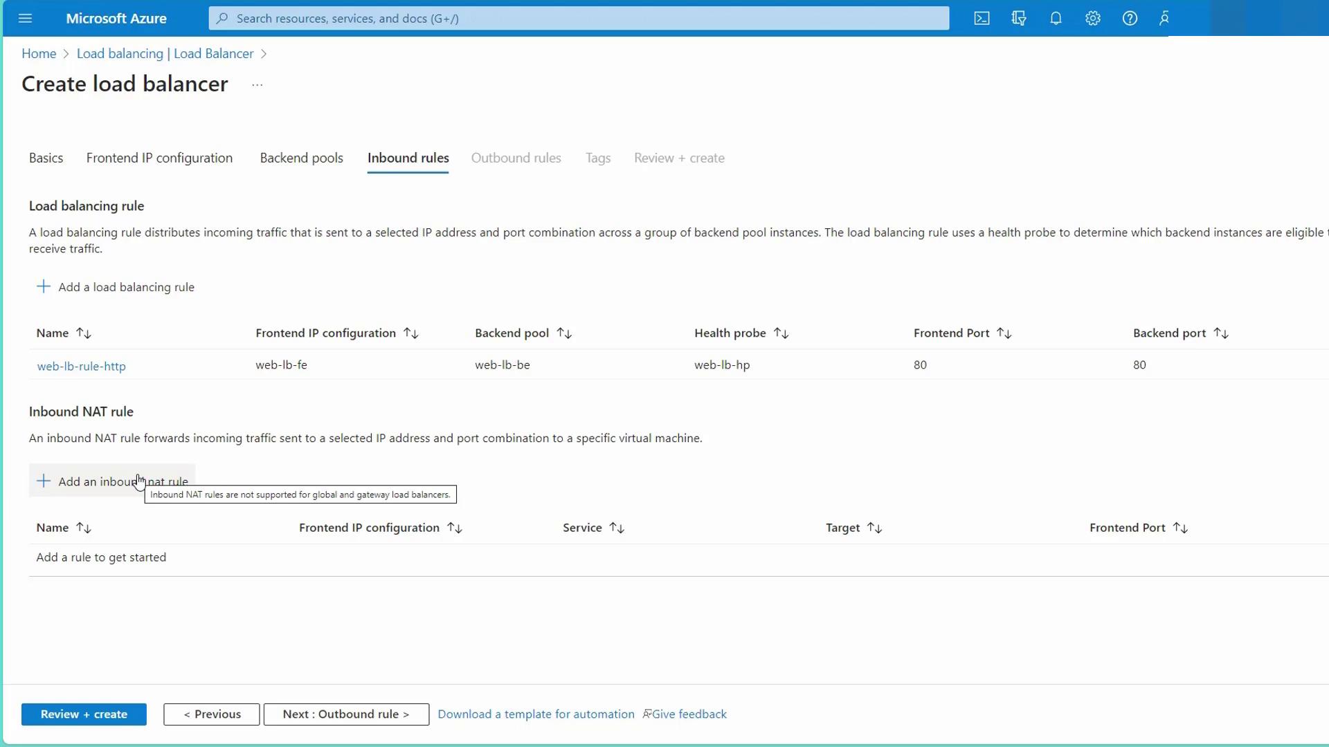
- Create Load Balancing Rules and Health Probes:
-
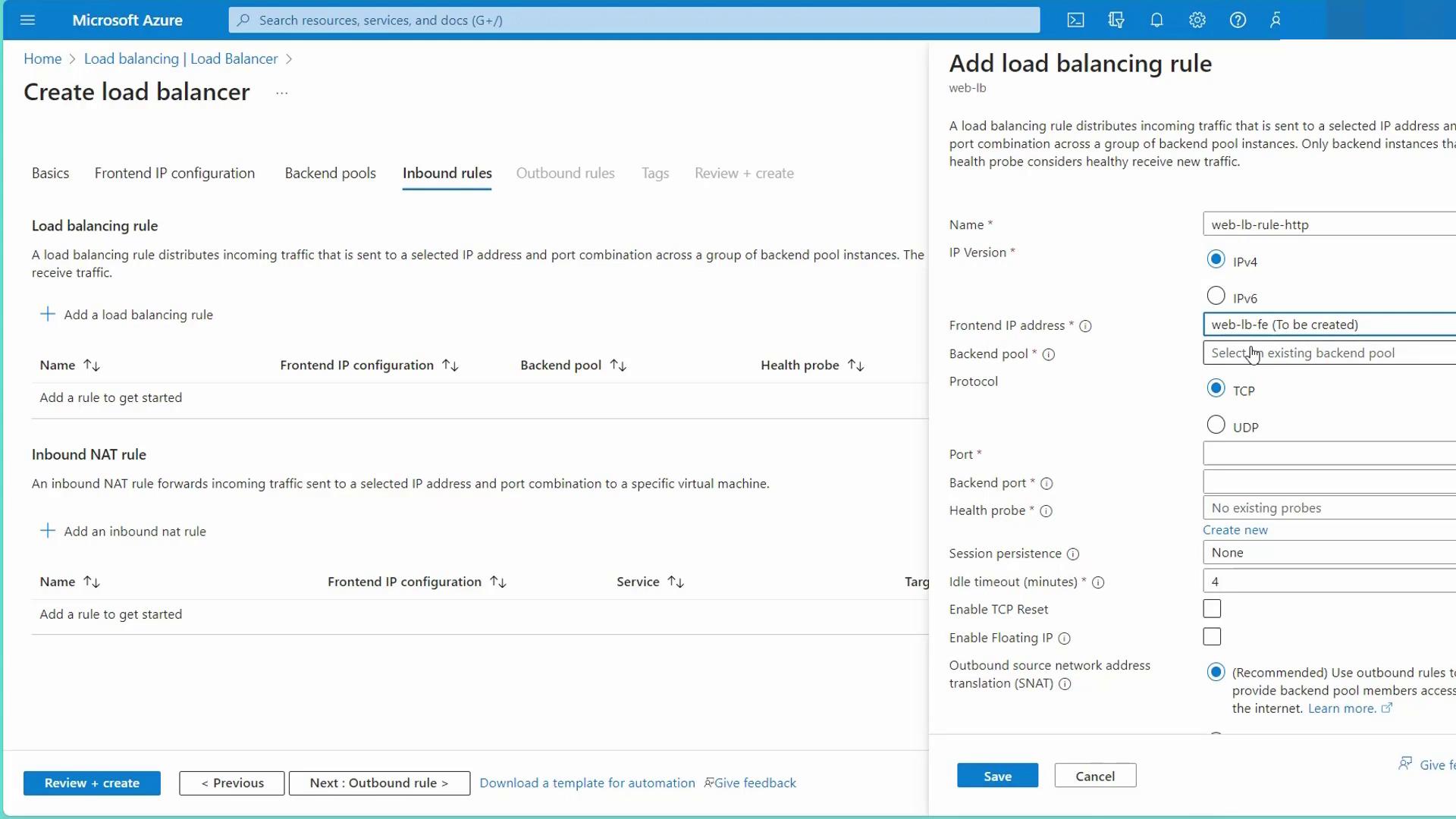
Load Balancing Rule:
Create a rule (e.g., “web LB rule HTTP”) that links the frontend IP to the backend pool. Configure the protocol settings:- Frontend port: 80
- Backend port: 80 (or another port if your web server listens on a different port, e.g., 8080)
- Protocol: TCP
- Session persistence: Choose either None (default, uses a five-tuple hash) or Client IP based for sticky sessions.
-
Health Probe:
Establish a health probe (e.g., “web LB HP”) that monitors backend server health. Choose between TCP (to check if the port is open) or HTTP (to send a web request expecting a 200 OK response). In this configuration, the probe checks the root path on port 80 every five seconds.
-
Load Balancing Rule:
- Configure Inbound NAT Rules (if needed):
Use inbound NAT rules to enable direct access (e.g., SSH) to individual backend servers by mapping unique frontend ports (such as 22 or 3000) to port 22 on specific backend instances.
- Review and Create the Load Balancer:
Double-check all settings (frontend, backend, load balancing rules, and health probes) and create the load balancer. The resulting configuration will share the public IP address among the web servers, facilitating the distribution of incoming traffic based on your defined rules.
Ensure that your NSG rules allow traffic on port 80 to avoid any disruption in load balancing functionality.