Microsoft Azure Security Technologies (AZ-500)
Perimeter Security
Explore hub and spoke topology
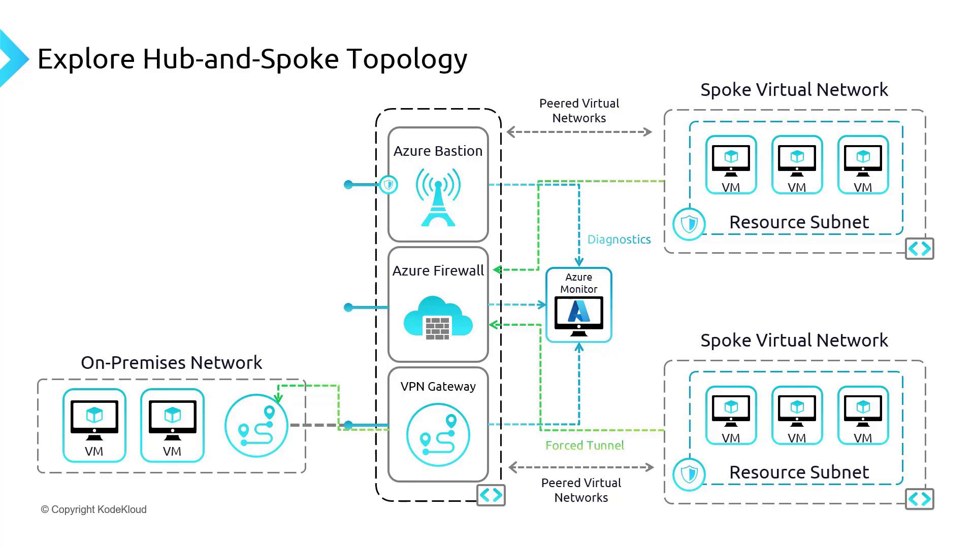
In this guide, we will explore a common hub-and-spoke network setup in Azure. In this architecture, the central hub virtual network (VNet) connects multiple spoke VNets. The hub hosts essential components such as Azure Firewall, Azure Bastion, and VPN Gateway, which secure and route traffic. Additionally, forced tunneling directs outbound traffic from the Azure Firewall to a network virtual appliance (NVA) or an on-premises firewall, ensuring that all traffic is properly inspected.
Think of the hub as a busy city center linking various suburban spokes. Azure Firewall, deployed in the hub, monitors and filters traffic, while Azure Bastion allows secure browser-based access (via SSH or RDP) to virtual machines directly through the Azure Portal. The VPN Gateway, meanwhile, creates an encrypted bridge between Azure and the on-premises network.
Below is a high-level diagram illustrating the overall hub-and-spoke topology:
Setting Up Network Rules and Route Tables
In this section, we'll configure network rules and route tables in the Azure Portal to enable seamless communication between Spoke A and Spoke B via the Azure Firewall.
Configuring the Route Table for Spoke B
In the Azure Portal, navigate to Route Table and create a new route table for Spoke B. Name it
Spoke BRT.After the deployment completes, verify that
Spoke BRTappears in the resource group's list.Open the routes section and add the following routes:
Route 1: Internal Communication
- Route Name: internal
- Destination Type: IP address
- Destination Address Prefix: 192.168.2.0/24 (the internal addresses of the spoke VNet)
- Next Hop Type: Virtual network
Route 2: Traffic to the Firewall
- Destination Type: IP address
- Destination Address Prefix: (Use appropriate IP address range for your environment)
- Next Hop Type: Virtual appliance
- Next Hop IP Address: 192.168.0.4 (this example represents the firewall appliance)
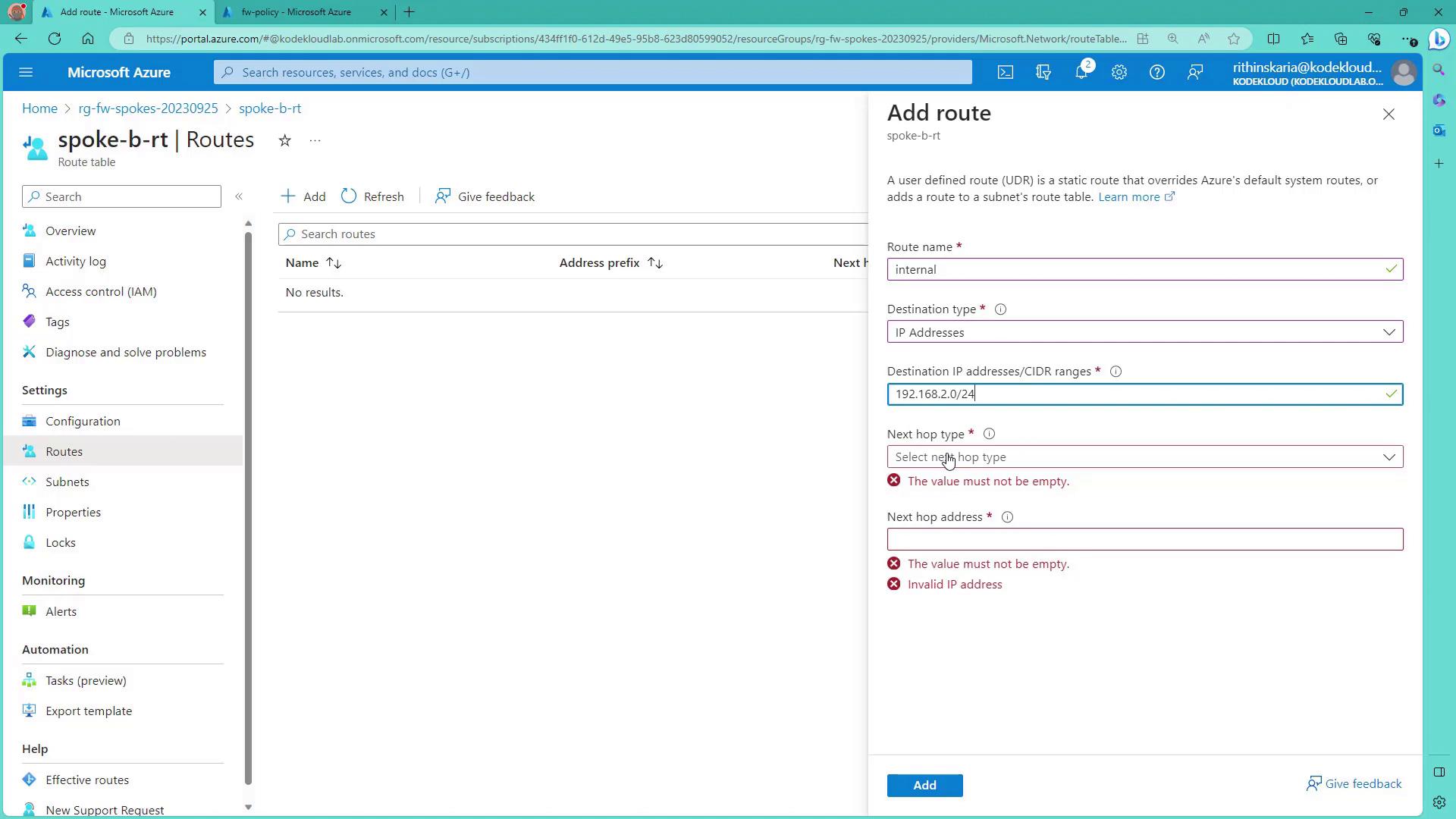
The image below shows the Azure Portal route table form with the required details:
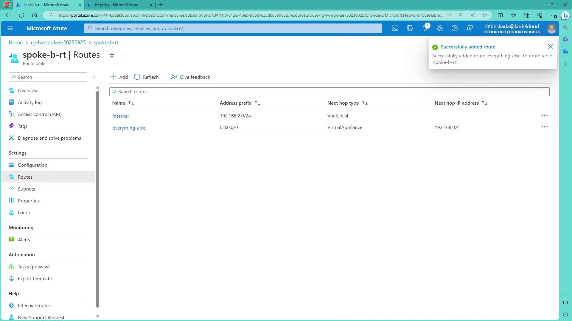
After entering the routes, verify that they appear correctly:
Testing Public IP Connectivity
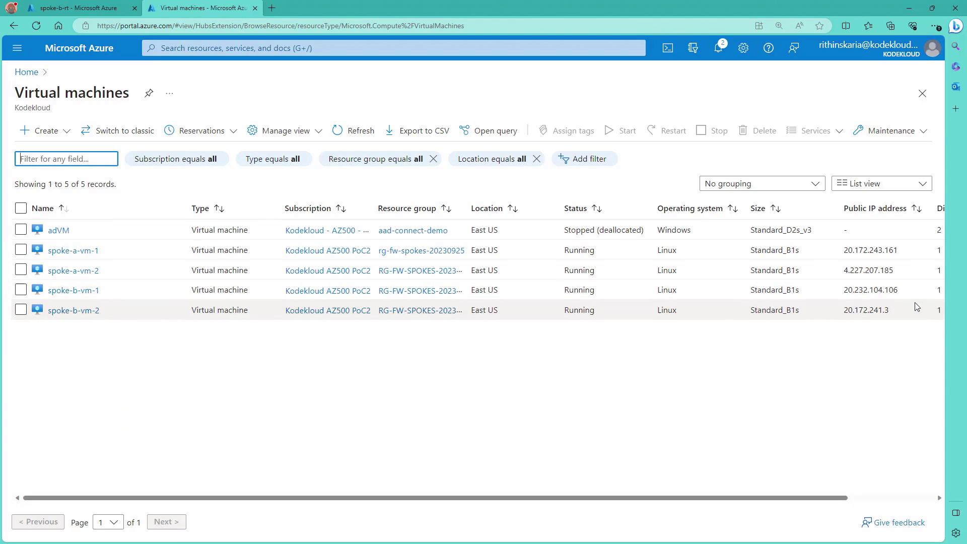
Before applying the new routing rules, test connectivity to the virtual machines via their public IP addresses. Start by selecting VM1 from the virtual machines list:
Open a terminal and connect to VM1 via SSH:
ssh [email protected]
Console output:
The authenticity of host '20.232.104.106 (20.232.104.106)' can't be established.
ED25519 key fingerprint is SHA256:MbBAyG1xPD5qTfWbzHMVB0PmbAQLMdgonRJyFeKX0.
This key is not known by any other names
Are you sure you want to continue connecting (yes/no)? yes
Warning: Permanently added '20.232.104.106' (ED25519) to the list of known hosts.
[email protected]'s password:
Once authenticated, you will be logged into VM1. After the route table is associated with the subnet (Spoke B, default subnet) carrying the spoke virtual machines, expect your connection to eventually disconnect—as traffic will now be routed through the firewall. This propagation might take a couple of minutes.
Connectivity Note
Ensure you have a backup connection method before applying routing changes to avoid losing access.
Configuring Azure Firewall Network Rules
Now, let's configure the Azure Firewall to allow permitted traffic between Spoke A and Spoke B using network rules.
- In the Azure Portal, navigate to the Firewall policy and select Network Rules.
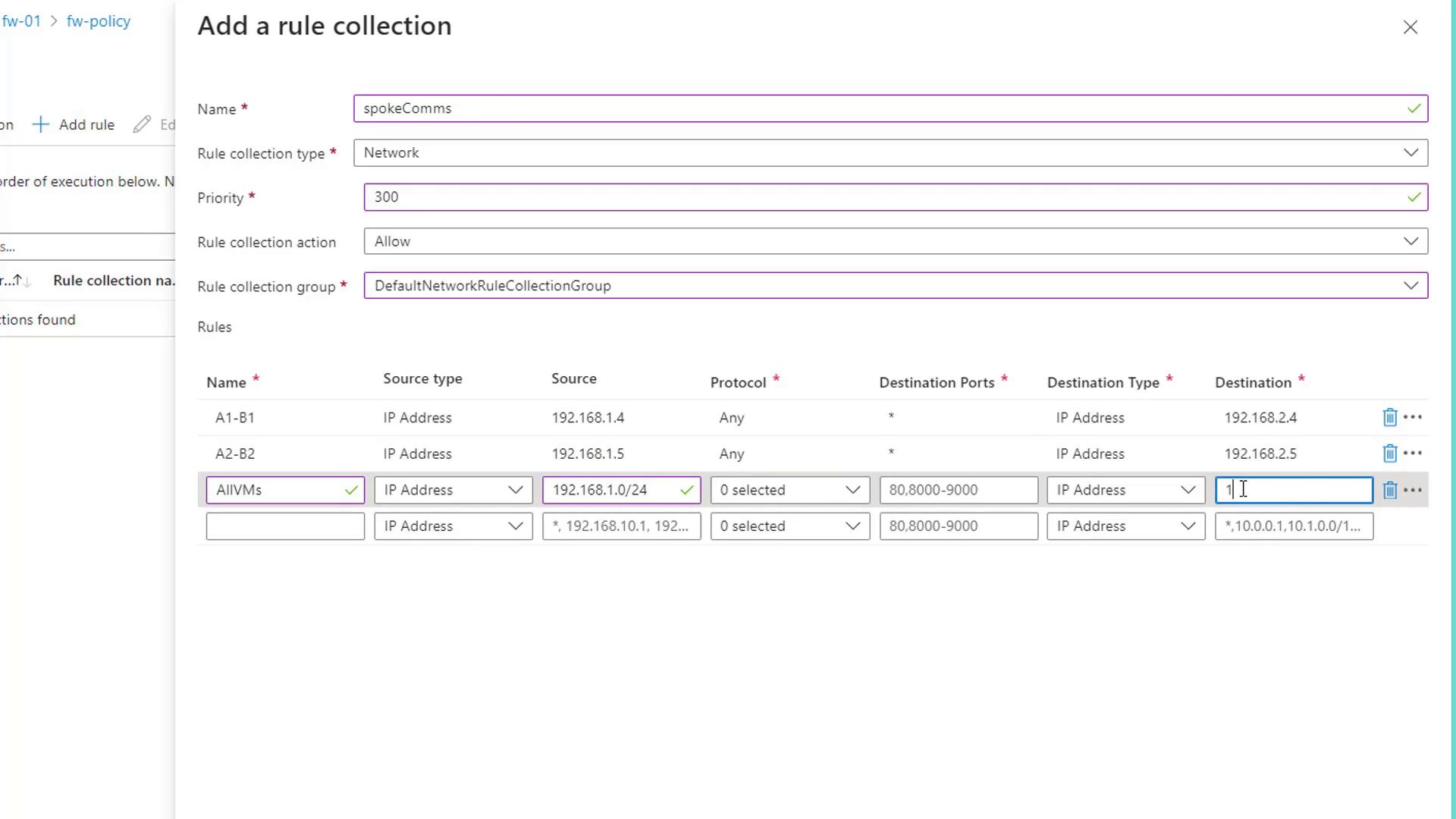
- Create a new rule collection (for example,
spoke comms) with the following settings:- Name: spoke comms
- Priority: 300
- Action: Allow
- Rule Collection Type: Default network rule collection group
Add the following rules to map Spoke A to Spoke B:
Rule A1 to B1:
- Source IP: 192.168.1.4
- Destination IP: 192.168.2.4
- Protocols: All
- Destination Port: Any
Rule A2 to B2:
- Source IP: 192.168.1.5
- Destination IP: 192.168.2.5
- Protocols: All
- Destination Port: Any
Stateful Firewall
Because Azure Firewall is stateful, you do not need to configure reverse rules. Once the outbound rule is matched, the return traffic is automatically allowed.
The diagram below visually represents the network rule configuration process:
After adding the network rules, allow a short period for the firewall to update its configuration.
Demonstrating Connectivity
To validate that the configured routes and firewall rules are working as expected, follow these steps:
1. From Spoke A to Spoke B VM
On a VM in Spoke A, ping the IP address of a VM in Spoke B (e.g., 192.168.2.4). A successful ping indicates that the firewall is correctly allowing the traffic.
ping 192.168.2.4
Sample output:
PING 192.168.2.4 (192.168.2.4) 56(84) bytes of data.
64 bytes from 192.168.2.4: icmp_seq=1 ttl=63 time=3.86 ms
64 bytes from 192.168.2.4: icmp_seq=2 ttl=63 time=3.09 ms
64 bytes from 192.168.2.4: icmp_seq=3 ttl=63 time=2.93 ms
64 bytes from 192.168.2.4: icmp_seq=4 ttl=63 time=4.01 ms
--- 192.168.2.4 ping statistics ---
4 packets transmitted, 4 received, 0% packet loss,
rtt min/avg/max/mdev = 2.926/3.470/4.013/0.470 ms
2. Testing a Blocked Connection
Attempt to ping an IP address (for example, 192.168.2.5) that does not have an allowed rule. Lack of reply confirms that only permitted traffic passes through.
ping 192.168.2.5
Expected output:
PING 192.168.2.5 (192.168.2.5) 56(84) bytes of data.
--- 192.168.2.5 ping statistics ---
4 packets transmitted, 0 received, 100% packet loss
3. Validating Reverse Traffic
From a VM in Spoke B, test connectivity back to a VM in Spoke A. For example, pinging 192.168.1.4 should succeed, while pinging another disallowed IP should fail.
ping 192.168.1.4
Sample output:
PING 192.168.1.4 (192.168.1.4) 56(84) bytes of data.
64 bytes from 192.168.1.4: icmp_seq=1 ttl=63 time=3.84 ms
64 bytes from 192.168.1.4: icmp_seq=2 ttl=63 time=3.77 ms
64 bytes from 192.168.1.4: icmp_seq=3 ttl=63 time=3.50 ms
--- 192.168.1.4 ping statistics ---
3 packets transmitted, 3 received, 0% packet loss
For additional application-level connectivity testing, you can use curl. For instance, accessing a website may be blocked if no matching rule exists:
curl www.google.com
The console might output:
Action: Deny. Reason: No rule matched. Proceeding with default action.
A successful ping from Spoke B to Spoke A further confirms that internal communications are functioning as configured.
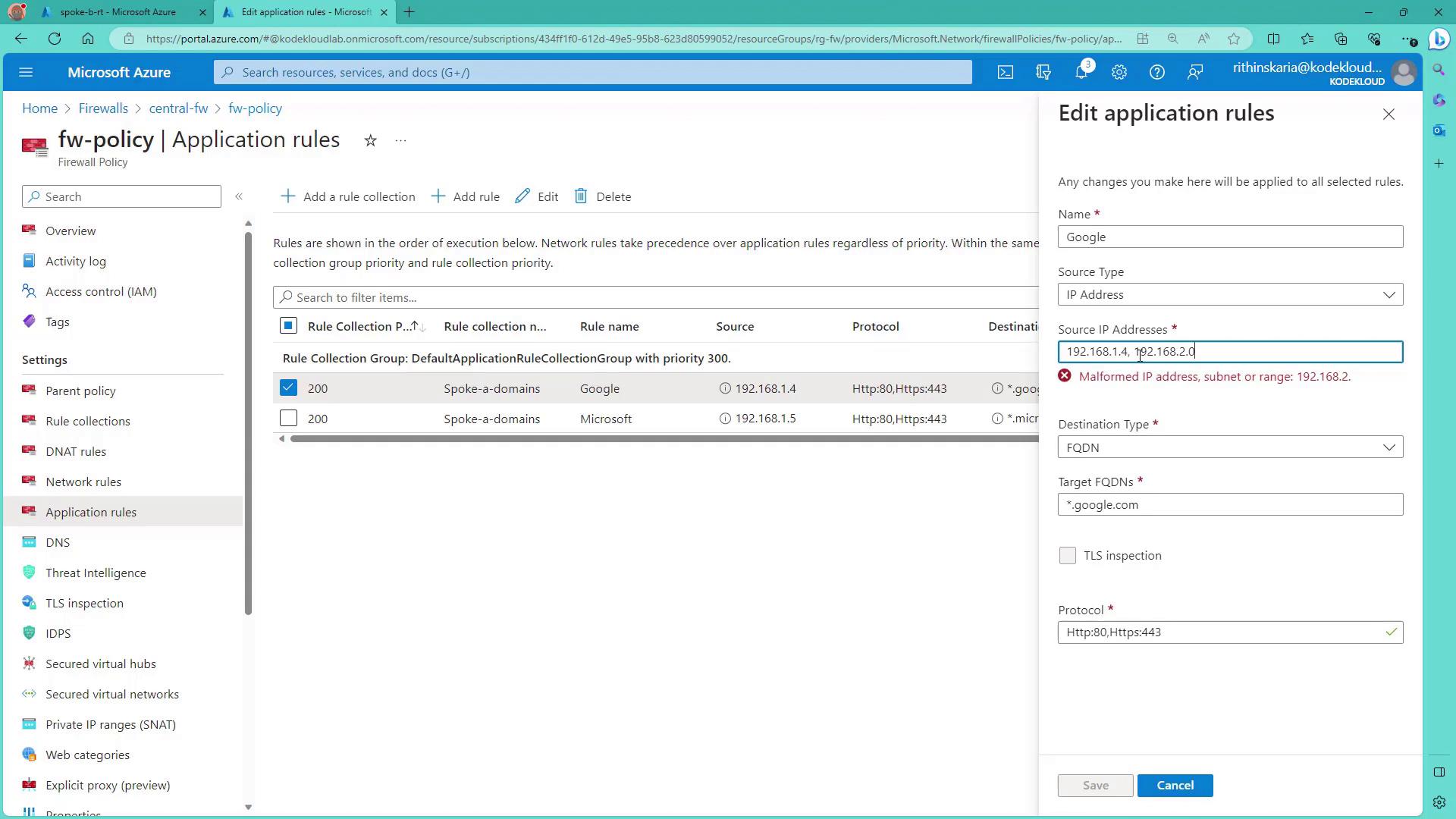
Modifying Application Rules for Outbound Access
To allow outbound web access (for example, to google.com), modify the application rules to include the required IP ranges. In our demo, we update the rule to allow traffic from the entire subnet 192.168.2.0/24 so that VMs in that subnet gain access to Google.
The image below displays the Azure Portal interface for managing firewall application rules:
After saving the updated configuration, test access again with:
ping 192.168.2.4
Sample output:
PING 192.168.2.4 (192.168.2.4) 56(84) bytes of data.
64 bytes from 192.168.2.4: icmp_seq=1 ttl=64 time=1.49 ms
64 bytes from 192.168.2.4: icmp_seq=2 ttl=64 time=1.25 ms
...
Since the updated rule only allows access for the specified subnet, attempts to reach websites outside this range (for example, www.microsoft.com) will be blocked.
For further testing, try:
curl www.microsoft.com
This command should fail due to the absence of a matching rule, while accessing www.google.com should succeed.
Extending the Architecture
In this demo, we focused on configuring Azure Firewall rules for internal communications between spokes. Additional components—such as VPN Gateway and Azure Bastion—further secure the network perimeter. Although on-premises connectivity via VPN has not been simulated here, the design provisions include:
- Defining a distinct address space for on-premises (e.g., 10.0.0.0/8)
- Directing traffic destined for on-premises to the virtual network gateway
With these configurations, you have implemented a robust and secure hub-and-spoke architecture in Azure. In upcoming articles, we will explore additional facets of network security and VPN connectivity.
This concludes our guide on creating a secure, well-managed hub-and-spoke architecture in Azure. Happy learning and secure your network!
Watch Video
Watch video content