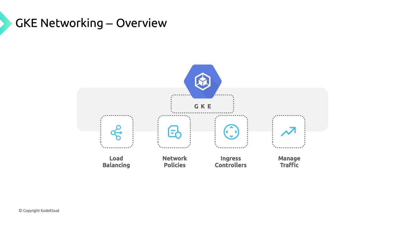
Core Networking Features in GKE
GKE includes built-in load balancing, network policies, and Ingress controllers to manage traffic flow:| Feature | Description | Example |
|---|---|---|
| Service Load Balancing | Automatically provision internal/external LBs | kubectl expose deployment nginx --port=80 |
| Network Policies | Define pod-to-pod and pod-to-external rules | kubectl apply -f network-policy.yaml |
| Ingress Controllers | HTTP(S) routing and host/path-based traffic rules | kubectl apply -f ingress-controller.yaml |
Cluster Connectivity Requirements
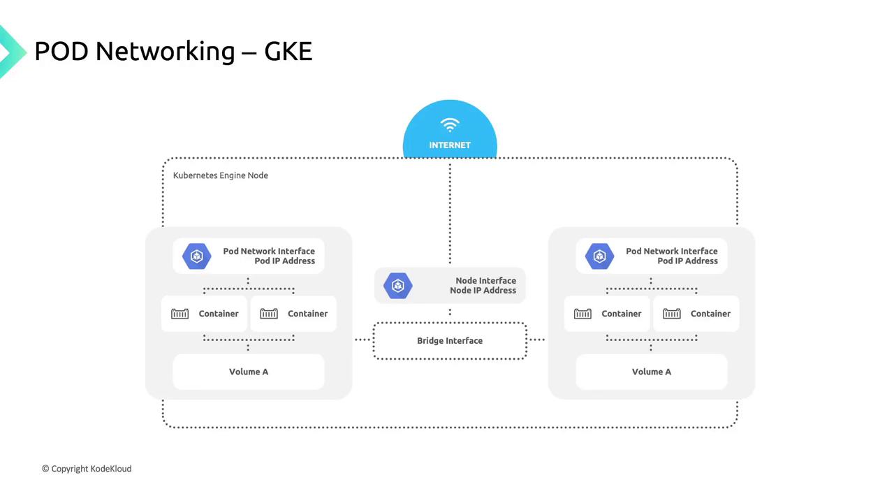
GKE clusters run within a Google Cloud VPC, giving you private isolation and direct access to Google services such as BigQuery and Cloud Storage. You can deploy:- Public clusters: Nodes have public IPs.
- Private clusters: Nodes use only private IPs and need Cloud NAT or proxy for internet egress.
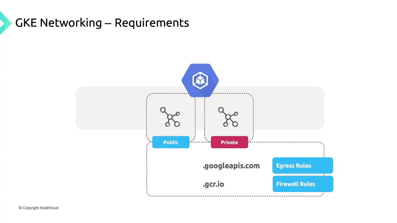
If you add high-priority firewall rules that block egress, you must explicitly allow:
*.googleapis.com*.gcr.io- The control plane IP address
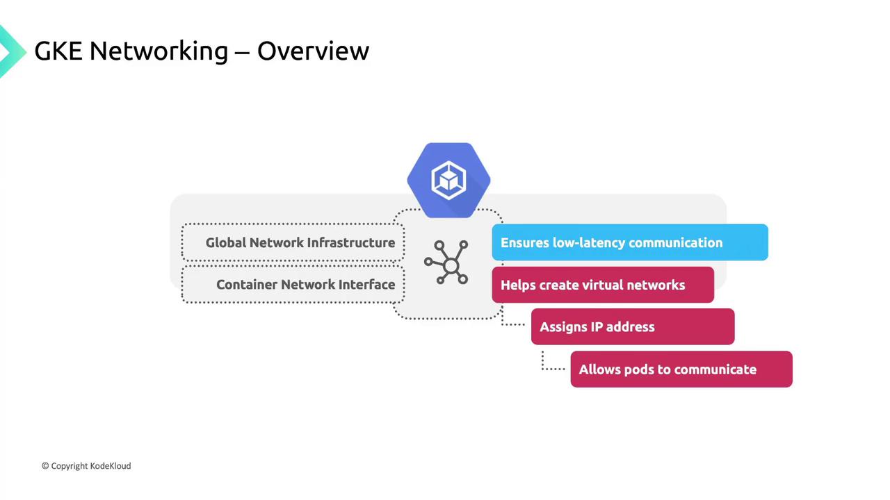
IP Address Allocation in GKE
Proper IP planning ensures each component has a unique address space. GKE allocates addresses for: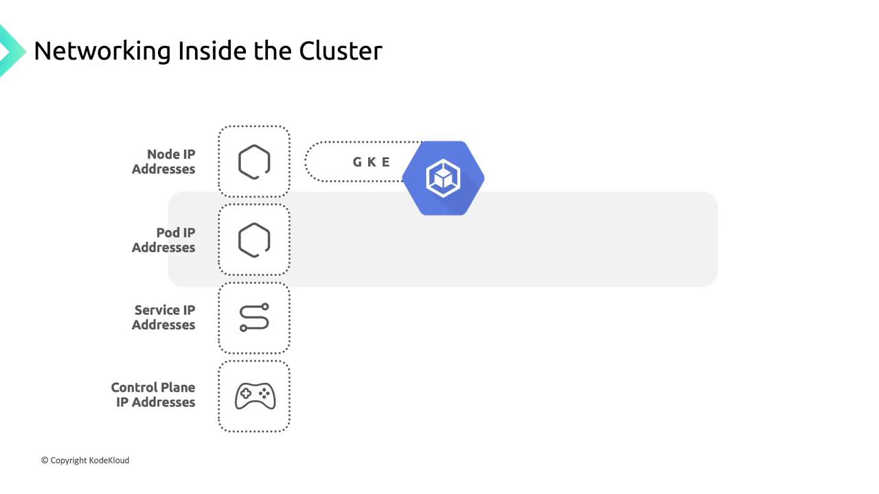
- Node IP Addresses: Assigned from the VPC to enable kubelet, kube-proxy, and system components to communicate with the API server.
- Pod IP Addresses:
- By default, each node gets a
/24CIDR block for pod IPs.
- By default, each node gets a
Use the flexible pod range feature to adjust the CIDR size per node pool.
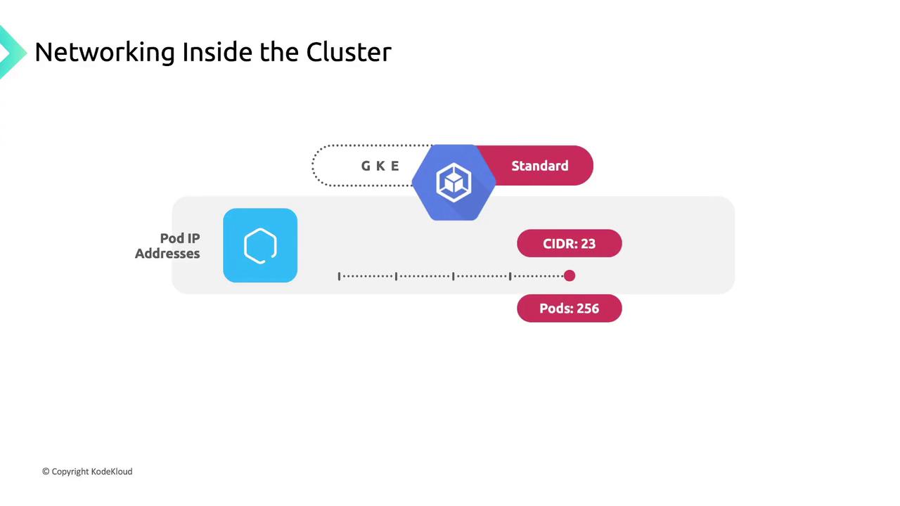
/23 block yields 512 addresses (up to 256 pods), though GKE Standard limits pods per node to 110 by default.3. Service IP Addresses: Each Service receives a stable Cluster IP from a dedicated pool.
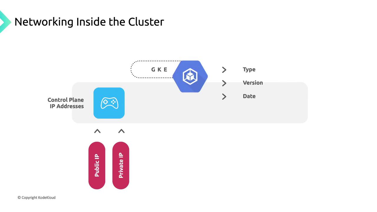
4. Control Plane IP Address: May be public or private based on cluster settings and version.
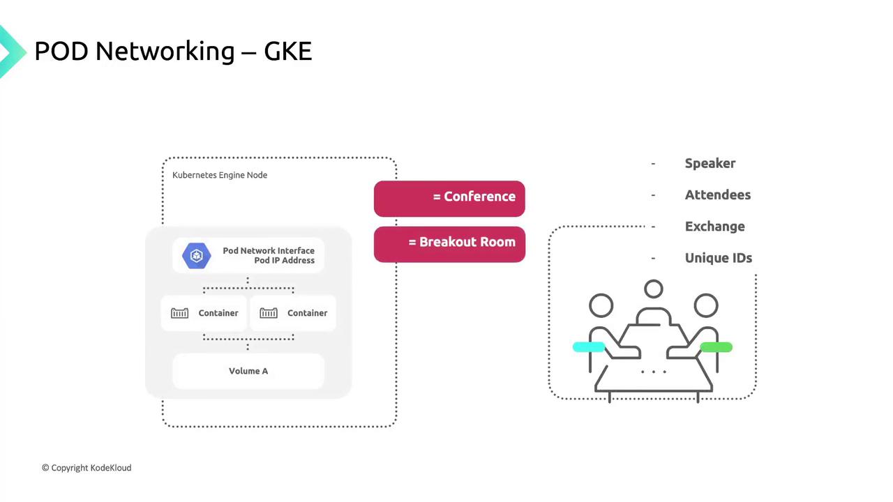
Pod Networking: A Conference Analogy
Think of a large conference with multiple breakout sessions. Each session has a dedicated speaker, and every participant has a unique badge number.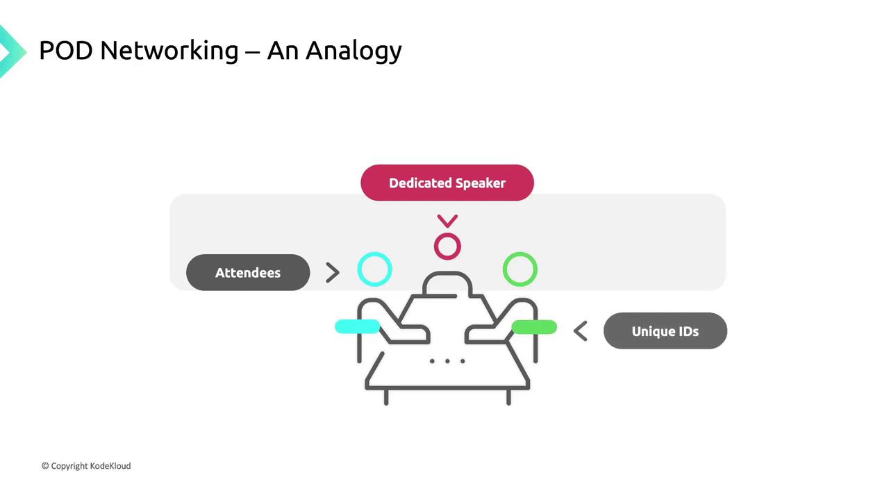
- Sessions (Pods): Units of work; each gets a unique IP “badge.”
- Rooms (Nodes): Physical hosts for sessions.
- Badges (IP Addresses): Ensure messages reach the correct session.
- A pod IP from the node’s CIDR block.
- A network namespace with a virtual Ethernet (veth) pair linked to the node’s
eth0. - Common volumes for storage.
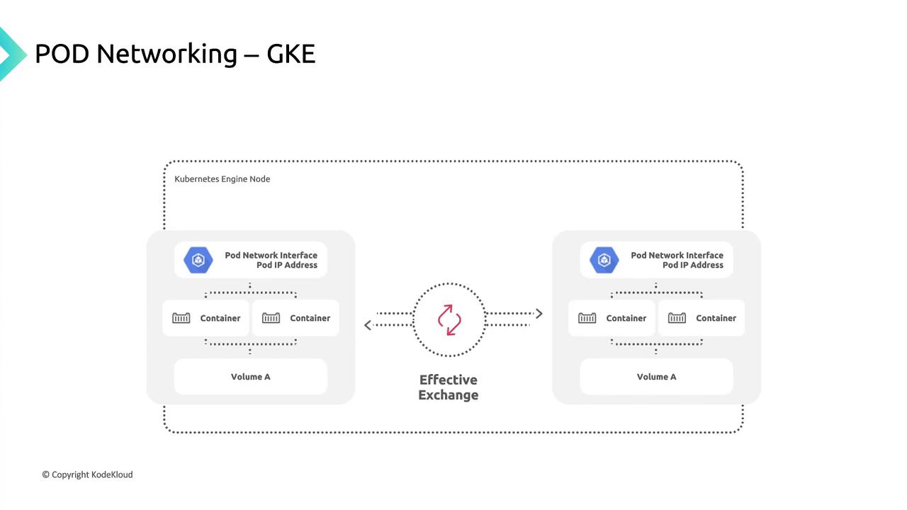
- It creates a network namespace on the node.
- Attaches the pod’s veth interface to the node network.
- Routes traffic seamlessly to and from the pod.
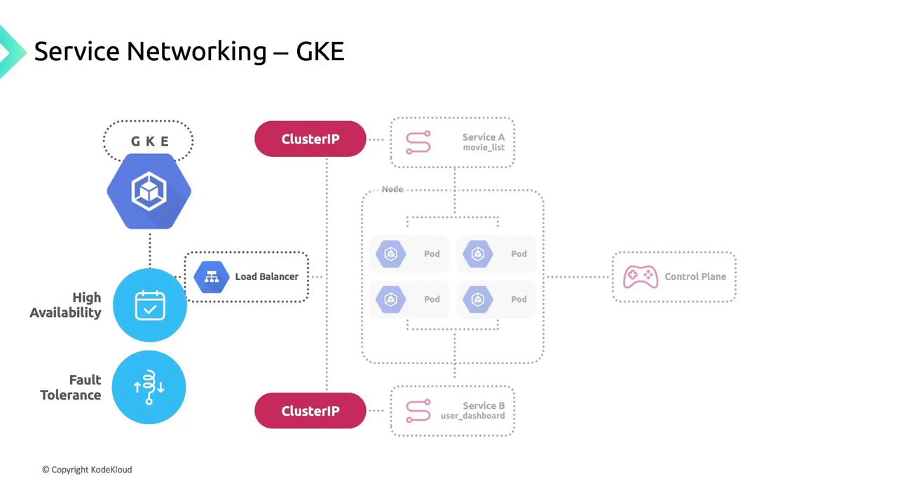
Service Networking
Kubernetes Services group pods using label selectors, providing:- A stable Cluster IP.
- A DNS entry for easy discovery.
- Built-in load balancing across healthy pods.
| Service Type | Description | Example |
|---|---|---|
| ClusterIP | Internal load balancing | kubectl expose deployment app --port=80 |
| NodePort | Exposes service on a node’s port | type: NodePort |
| LoadBalancer | Provisions a GCP external LB | type: LoadBalancer |
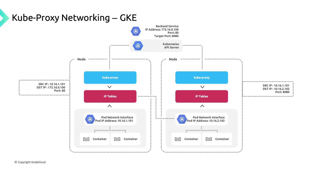
kube-proxy and Traffic Flow
GKE deploys kube-proxy as a DaemonSet so each node runs an instance that:- Watches the Kubernetes API for Service-to-pod endpoint mappings.
- Updates iptables rules (DNAT) on the node.
- Routes Service IP traffic to healthy pod IPs.
170.16.0.100:80, kube-proxy:
- Selects a healthy endpoint (e.g.,
10.16.2.102:8080). - Applies a DNAT rule to forward the packet.