Application Architecture Overview
Our sample application consists of three layers running in separate namespaces:- Front-end: An Nginx server serving static assets and proxying requests.
- Back-end API: Node.js microservices handling business logic.
- Database: A MySQL instance persisting user data.
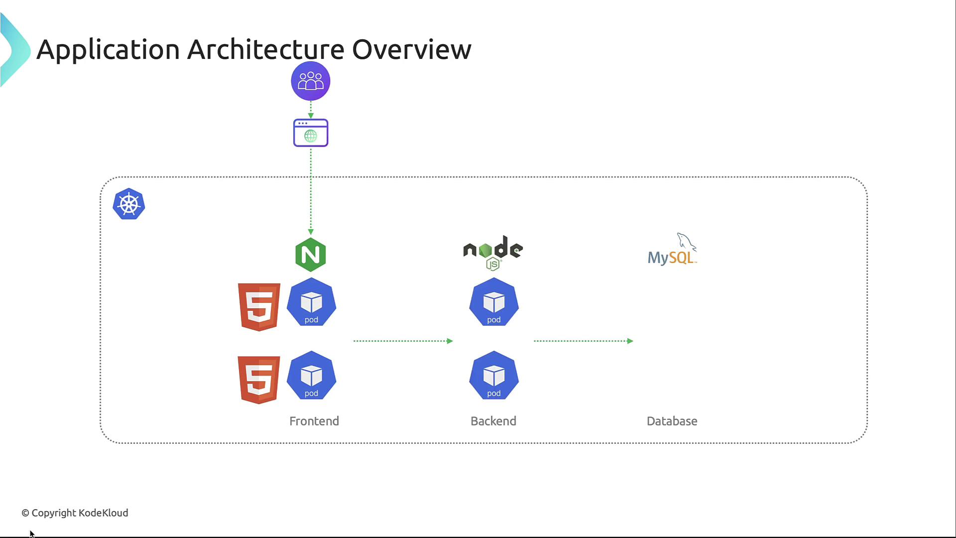
Front-end (frontend namespace)
This Nginx pod delivers HTML, CSS, and JavaScript while terminating TLS and enforcing authentication before proxying to backend services.Back-end API (backend namespace)
Node.js pods implement RESTful endpoints, perform request validation, and interact with the database using least-privilege credentials.Database (database namespace)
A single MySQL pod stores application state. Connections are encrypted and authenticated with narrow permissions.Threat Modeling Process
Threat modeling identifies, prioritizes, and mitigates security risks early:- Identify potential threats—enumerate attack scenarios.
- Assess impact—evaluate risk severity and likelihood.
- Implement countermeasures—design controls to reduce risk.
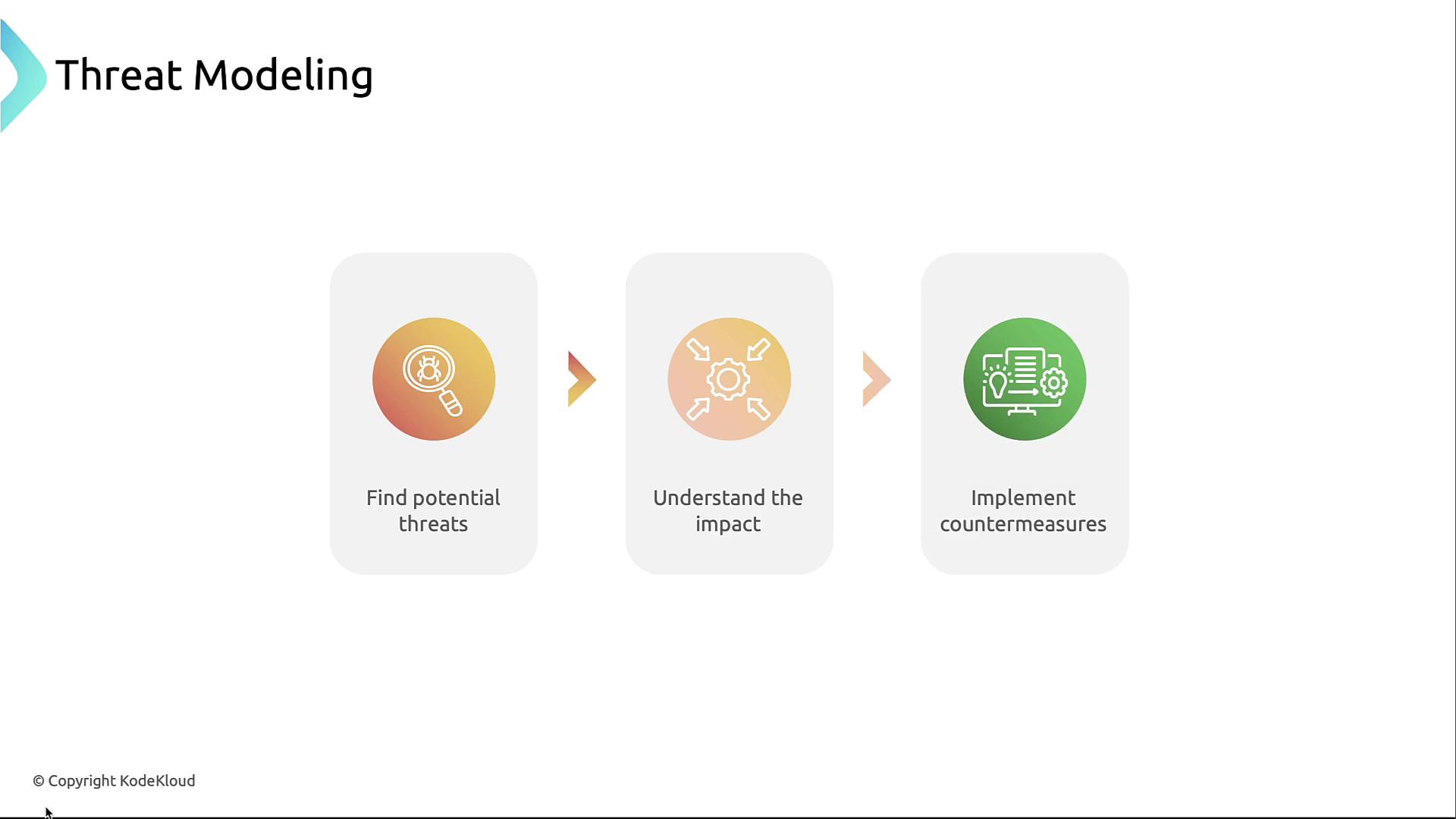
Threat modeling is iterative. Revisit your diagrams and controls whenever the application architecture changes.
Defining Trust Boundaries
To prevent lateral movement and data exfiltration, segment your cluster into distinct trust zones.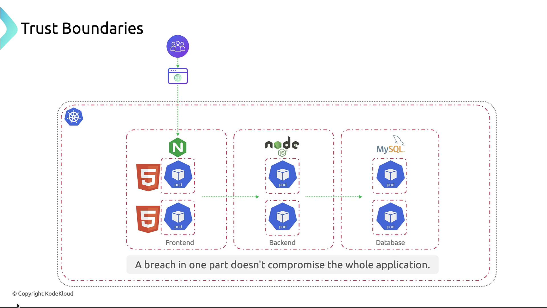
1. Cluster Boundary
Using separate clusters for dev, staging, and prod isolates environments at the highest level.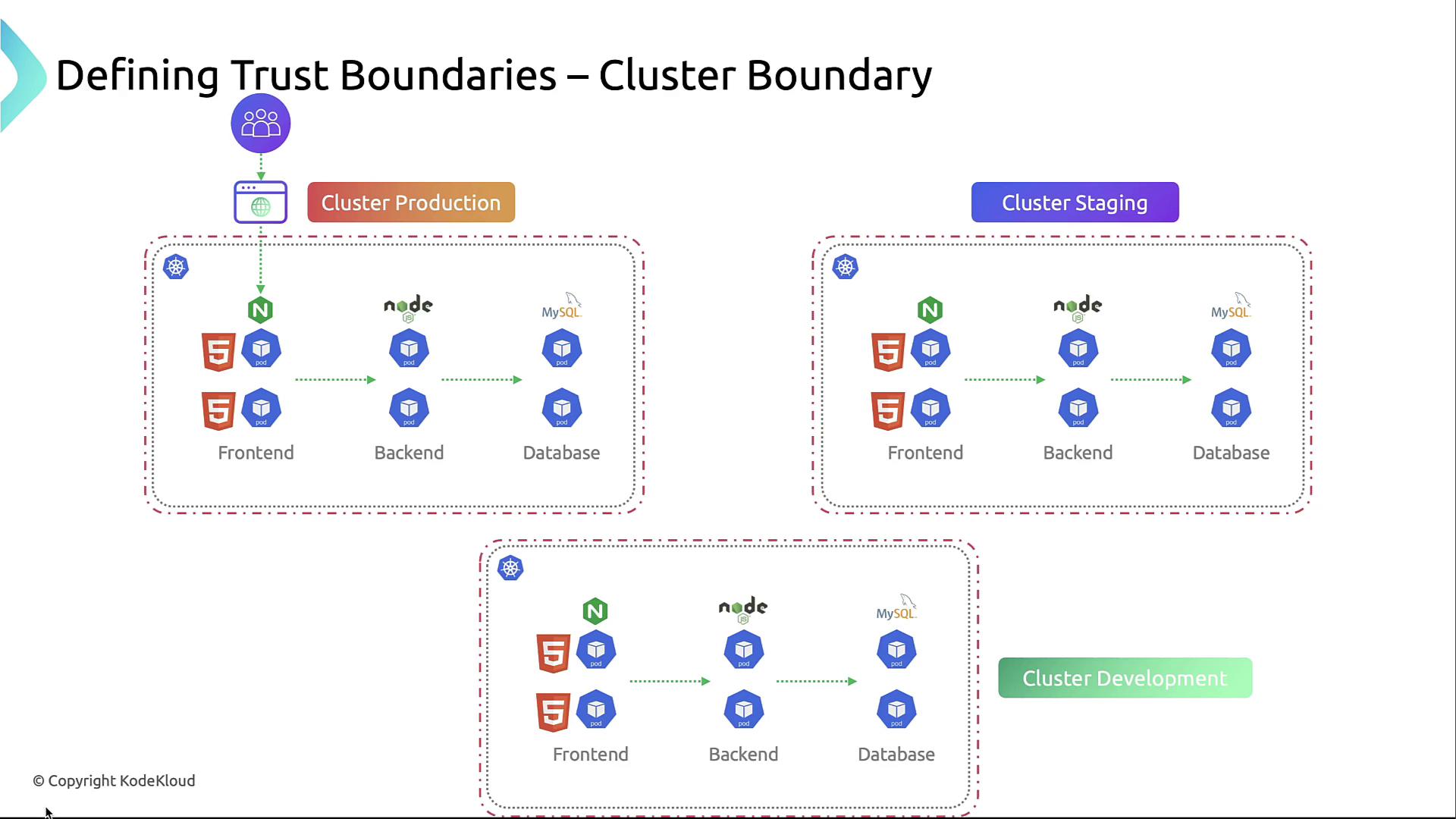
2. Node Boundary
Each node is a compute-level boundary. Harden kubelet, restrict SSH, and apply host-based firewalls so a compromised node doesn’t expose others.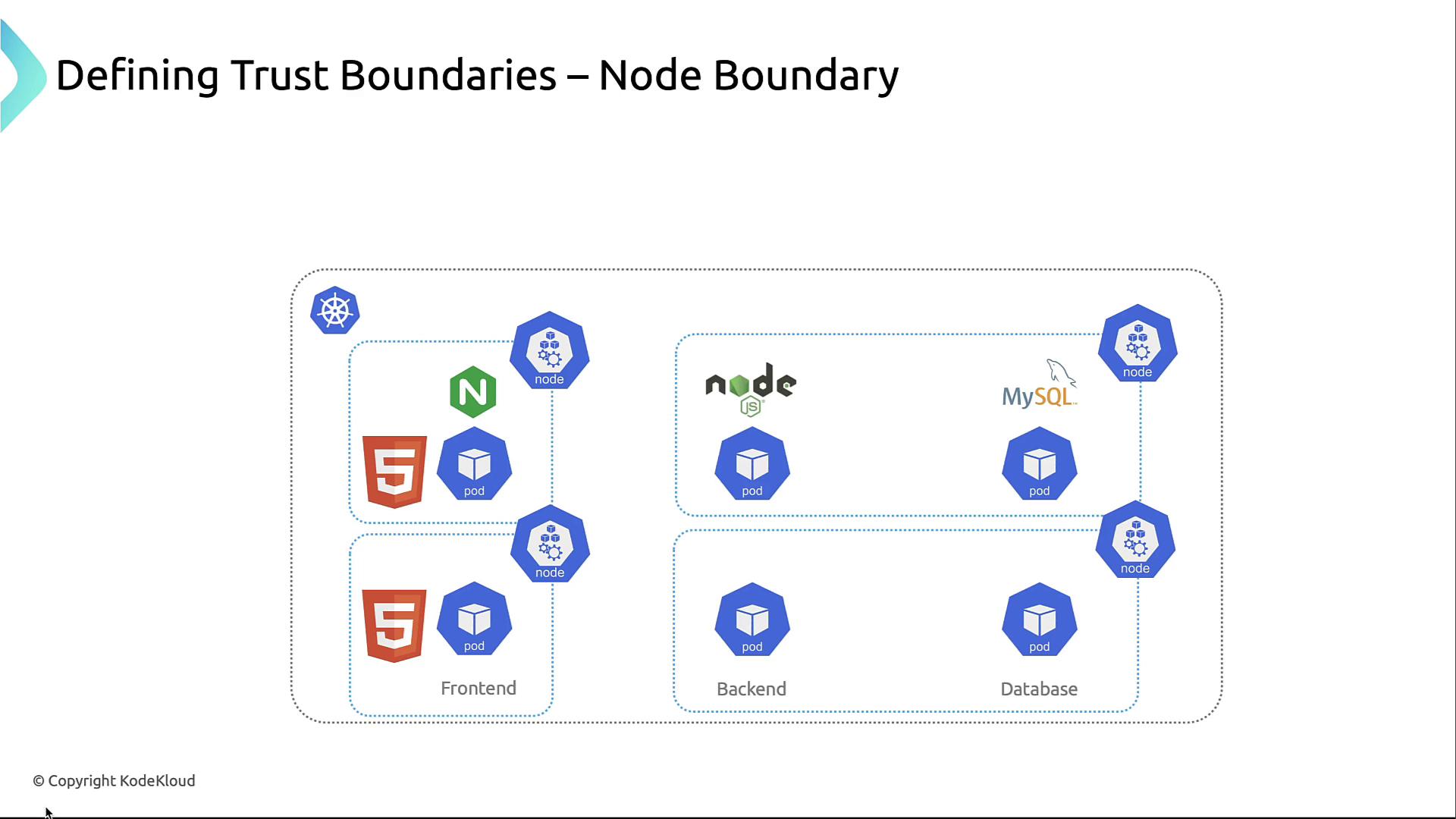
3. Namespace Boundary
Namespaces group related workloads and serve as the primary authorization unit. Use RBAC and NetworkPolicies to enforce least privilege.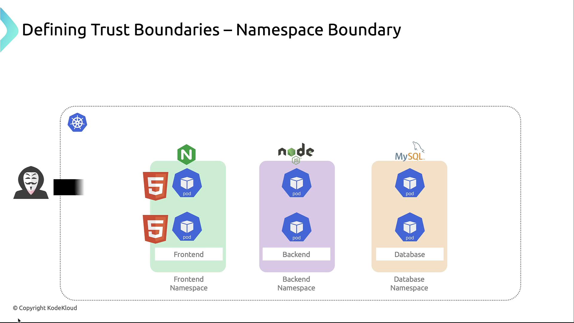
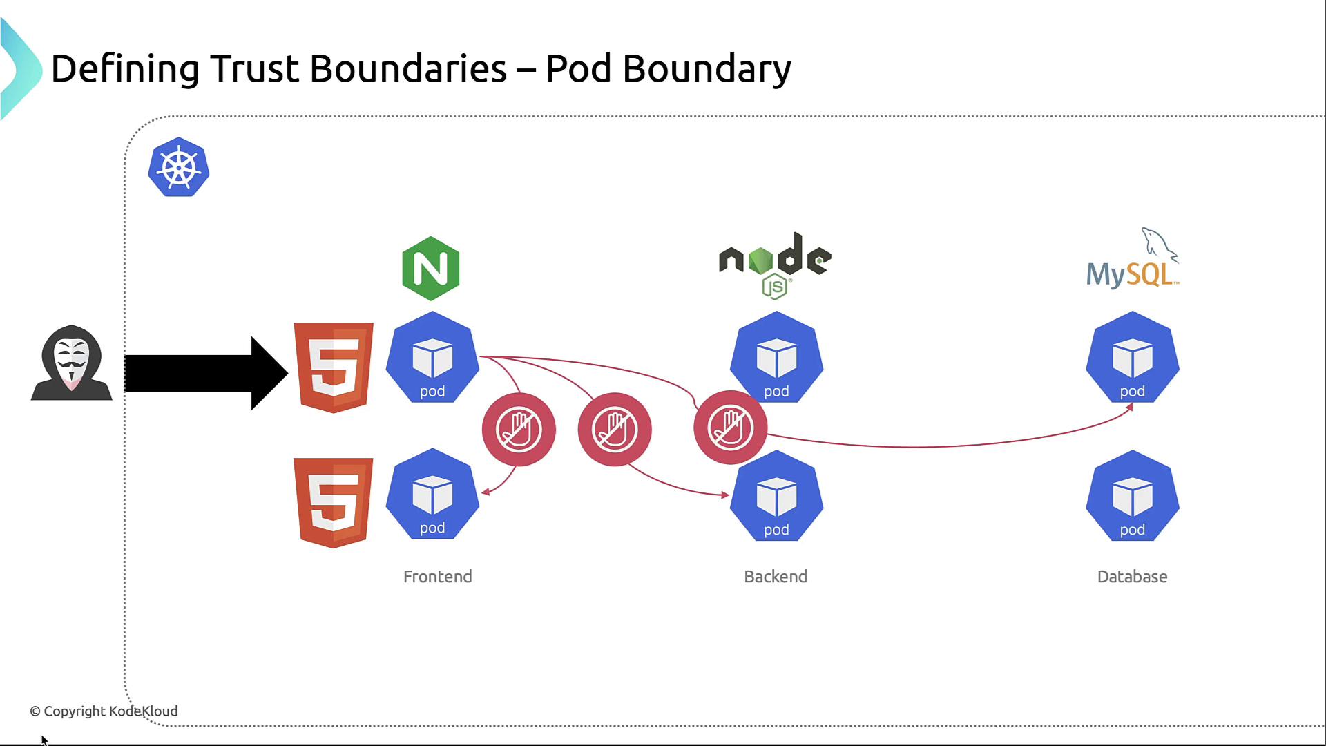
4. Pod Boundary
Each pod defines a network and security context. Use NetworkPolicies to prevent unrestricted pod-to-pod traffic.By default, Kubernetes allows all pod-to-pod communication. Without NetworkPolicies, an attacker can move laterally across pods.
5. Container Boundary
Within pods, container runtimes enforce isolation. Sidecar patterns and runtime policies (AppArmor, seccomp) reduce risk of breakout between containers.Trust Boundary Summary
| Trust Boundary | Scope | Example Controls |
|---|---|---|
| Cluster | Entire Kubernetes cluster | VPC segregation, dedicated clusters |
| Node | Single compute host | Node hardening, kubelet auth, host OS patches |
| Namespace | Logical partition | RBAC roles, NetworkPolicies |
| Pod | Application instance | PodSecurityPolicies, egress/ingress policies |
| Container | Container process | AppArmor, seccomp, minimal base images |
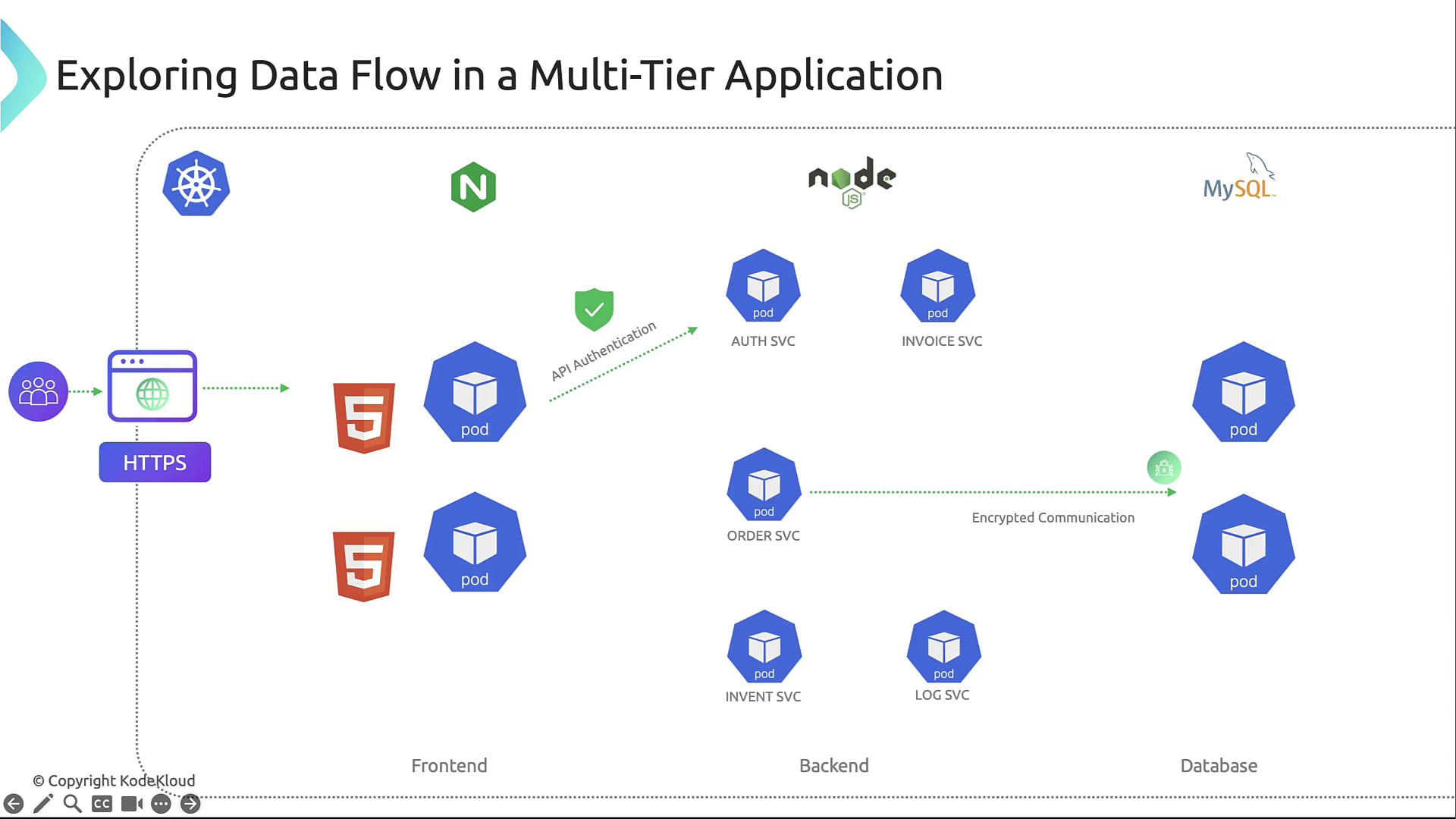
Data Flow in the Application
Understanding data flow helps place security controls where they matter most:- User → Front-end (Nginx): HTTPS termination, certificate validation, authentication.
- Front-end → Back-end APIs: mTLS or HTTPS with API tokens or OAuth.
- Back-end APIs → Database: Encrypted connections, least-privilege SQL accounts.
- Inter-service: Microservices communicate over the cluster network; NetworkPolicies restrict to necessary paths.
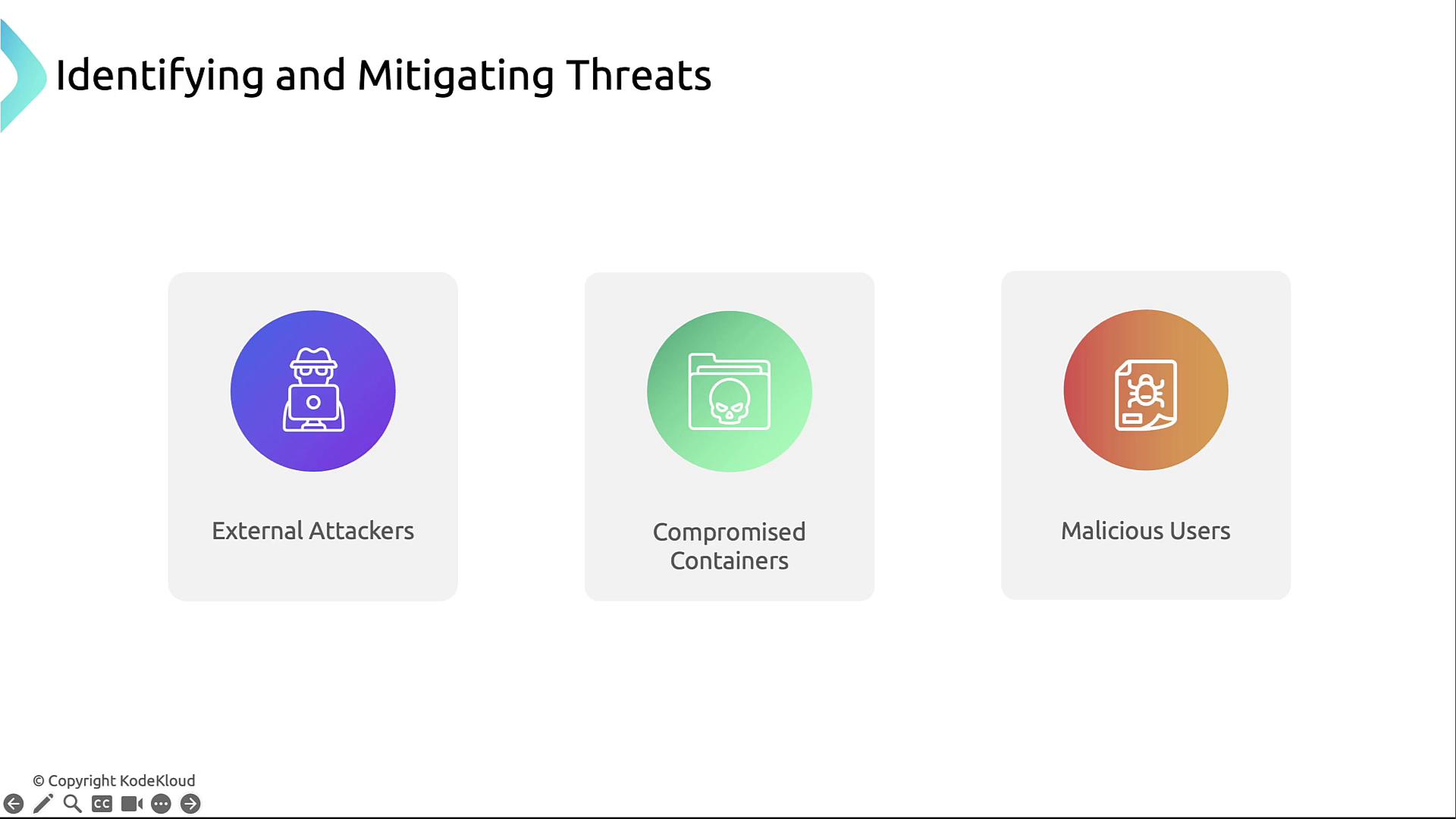
Common Threat Actors
- External Attackers: Scanning for exposed endpoints.
- Compromised Containers: Exploited via vulnerabilities or misconfigurations.
- Malicious Users: Insiders abusing privileges.