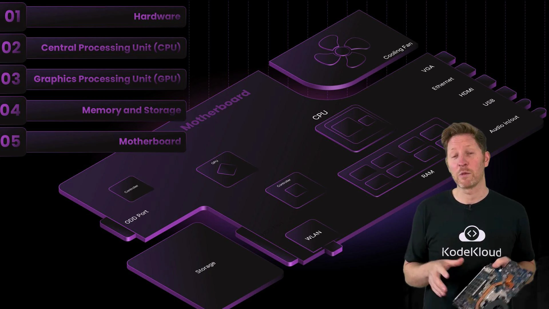
Welcome back to the computer architecture course. This lesson focuses on the motherboard: how it’s powered, how it stays cool, and how it coordinates every component in the system. You’re about to install a new RAM module as part of a memory upgrade for your team. At first glance the motherboard may look like a dense, confusing grid — but it’s a deliberate design of components and pathways that route power, data, and control signals. Before we explore the board’s controllers and buses, let’s install the RAM and observe the board’s structure in context. When installing RAM, note the keyed notch on the module that aligns with the slot so the stick can’t be inserted the wrong way. This prevents mechanical damage and improper electrical contact.Documentation Index
Fetch the complete documentation index at: https://notes.kodekloud.com/llms.txt
Use this file to discover all available pages before exploring further.
- Explain how power affects data retention and system stability.
- Describe cooling strategies that prevent thermal throttling and preserve performance.
- Identify key physical interfaces: ports, connectors, and expansion slots.
- Explain how system buses and controller chips coordinate communication between components.
When you install RAM, align the module’s notch with the slot key and press firmly until the latches click. If a module won’t seat, don’t force it — double-check orientation and the slot’s retention clips.
| Power source | Where it connects | Role |
|---|---|---|
| Main battery connector | Large plug on the motherboard | Provides mobile power when unplugged; prevents abrupt shutdowns |
| DC power input (charger) | External jack | Supplies mains power and charges the main battery |
- Volatile memory (RAM and caches) requires continuous power; contents are lost on power removal.
- Non-volatile storage (SSDs, HDDs, NVMe) retains data without power.
Avoid removing or inserting components with the main battery and charger connected. Static discharge or accidental shorting can damage VRMs, memory modules, and other sensitive components.
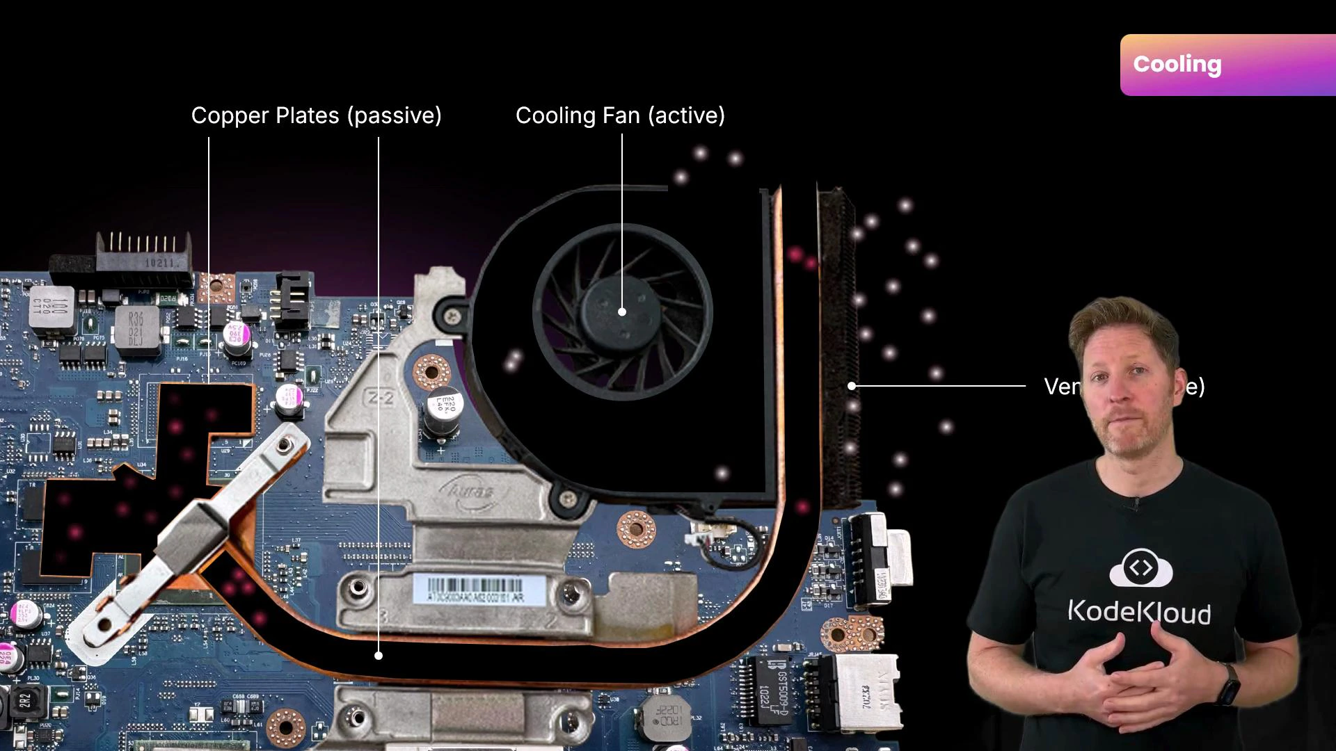
- Passive cooling — moves heat from chips to a common sink using heat spreaders (metal plates), heat pipes (typically copper), and thermal interface materials (thermal paste or pads).
- Active cooling — uses fans (or pumps in liquid systems) to expel heat from the chassis into the environment.
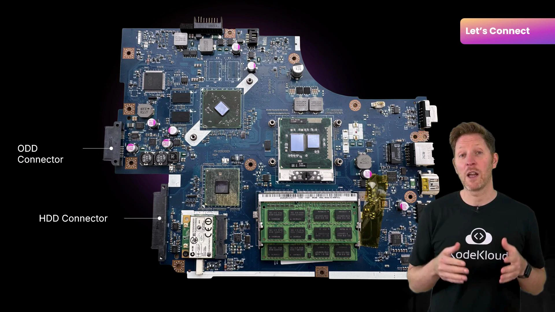
| Interface type | Purpose | Common examples |
|---|---|---|
| Ports (external) | Connect peripherals and displays | HDMI, USB, Ethernet, audio jacks |
| Connectors (internal) | Plug internal drives and power connections | SATA, M.2 sockets, power headers |
| Expansion slots | Add or upgrade internal cards/modules | DIMM (RAM), PCIe (GPU, NVMe adapters), M.2 for WLAN |
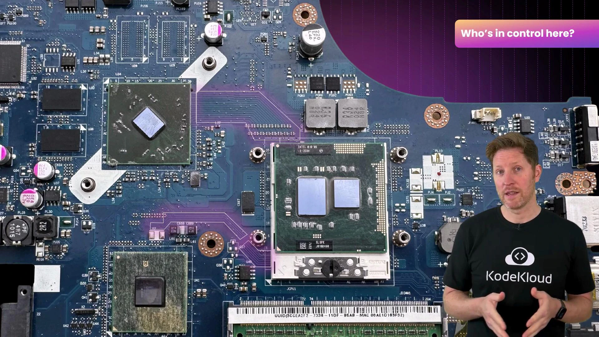
- Enumerating devices during boot (detecting hardware).
- Converting protocols (e.g., PCIe to SATA).
- Managing interrupts, DMA transfers, and power states.
- Firmware initializes the CPU and base chipset functions.
- RAM is prepared as temporary working memory for code and data.
- Connected devices (storage, GPUs, I/O) are detected and enumerated by controllers.
- Firmware locates the boot loader on the selected device; the boot loader loads the OS into RAM.
- Once the OS takes over, it loads drivers, initializes higher-level services, and presents the user interface.
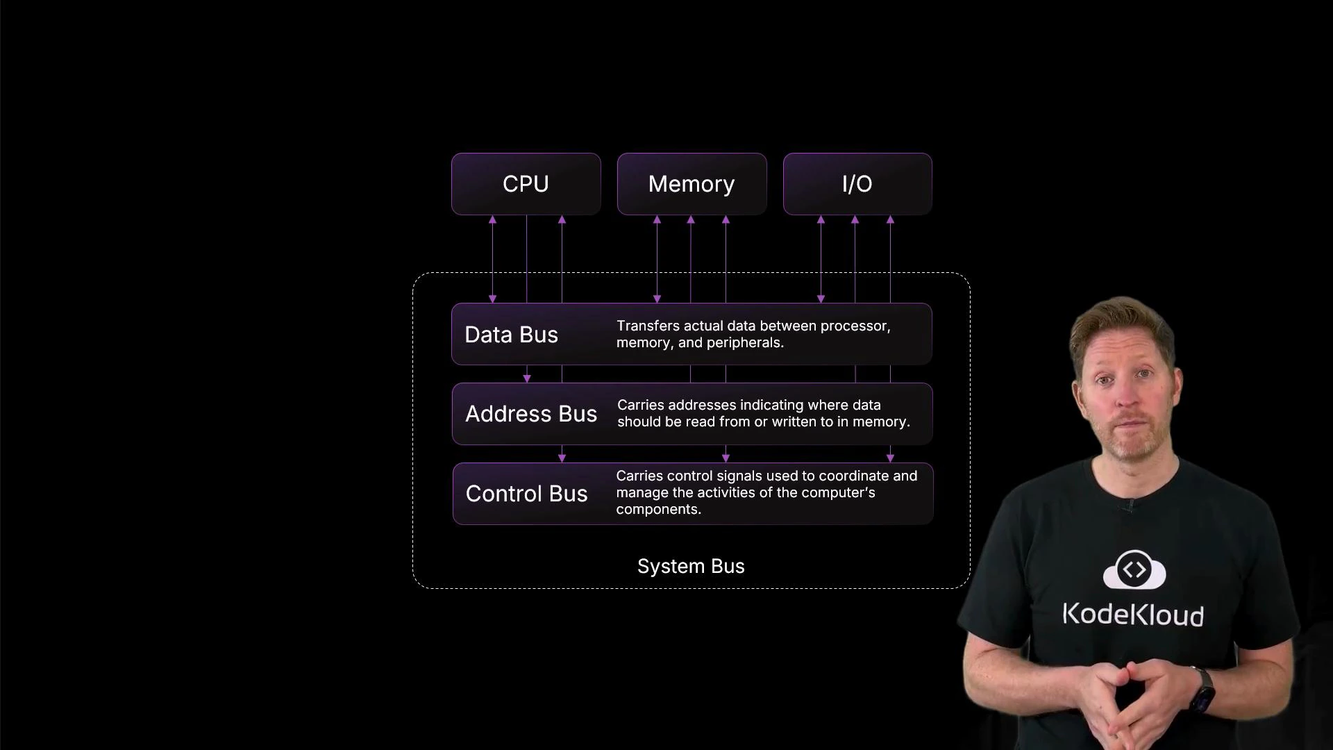
| Bus type | Direction | Primary role |
|---|---|---|
| Address bus | Unidirectional (CPU → memory/device) | Specifies the memory or device address for read/write operations |
| Data bus | Bidirectional | Carries actual data between CPU, memory, and I/O |
| Control bus | Bidirectional | Transmits control signals (read/write flags, interrupts, clock) to coordinate actions |
- Bus width — the number of parallel lines (like lanes on a highway). Wider buses move more bits per cycle.
- Word size — the CPU’s data unit size (e.g., 32-bit or 64-bit). Larger word sizes let each CPU operation move more data.
- The CPU places the photo’s memory address on the address bus.
- The CPU issues a read command on the control bus.
- Memory puts the requested data onto the data bus.
- The CPU processes the data and forwards results to the GPU/display subsystem to render the image.
- Power stability protects volatile data and prevents corruption during writes.
- Effective cooling preserves sustained performance and avoids thermal throttling.
- Physical interfaces (ports, connectors, slots) provide upgrade paths and external connectivity.
- Controllers and buses coordinate the complex choreography of data and control signals across the board.
- System buses (address, data, control) coordinate communication between CPU, memory, and I/O.
- Bus width and word size determine how much data can move per cycle.
- Stable power is essential: volatile memory loses data without power; backup batteries preserve clocks and minimal state.
- Passive and active cooling move and remove heat to prevent throttling and hardware damage.
- Ports, connectors, expansion slots, and controller chips provide the physical and logical interfaces that let components work together.