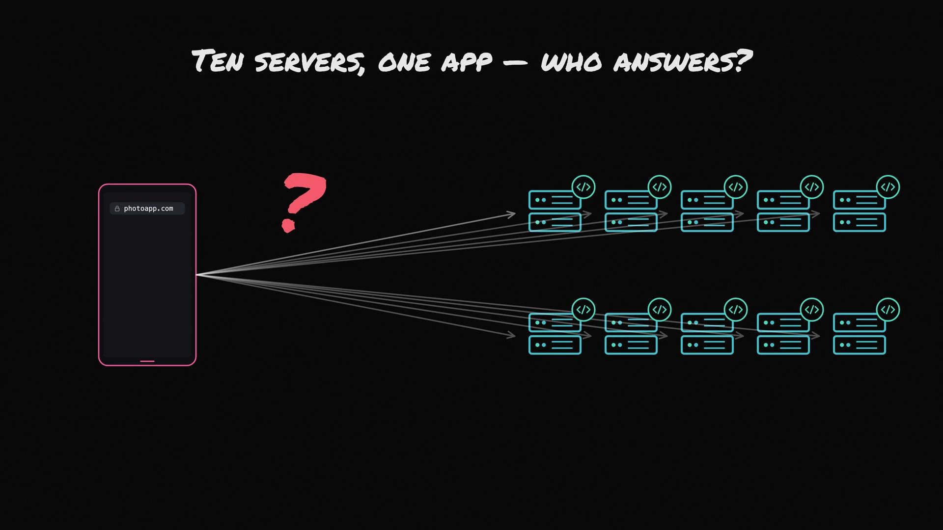
Your photo app now runs on several servers — each one a copy of the app. When a user opens the app, which of the ten servers actually answers the request?
The image depicts a mobile device accessing "photoapp.com" with its requests being routed to ten different servers, posing the question "Who answers?"
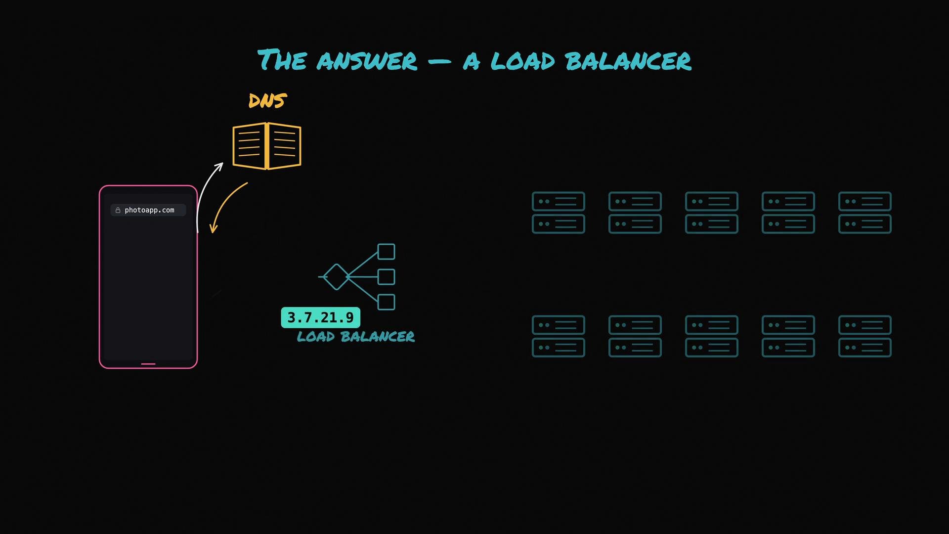
You want the user to interact with a single IP address, not ten. That single public endpoint is the load balancer. Start by tracing what happens when someone opens the app: the client performs a DNS lookup — “Where is photoapp.com?” DNS responds with an IP (or multiple IPs). That IP points to the load balancer, not directly to any of your application servers.
The image illustrates a network diagram involving DNS, a load balancer, and server clusters, suggesting how a request to "photoapp.com" is managed.
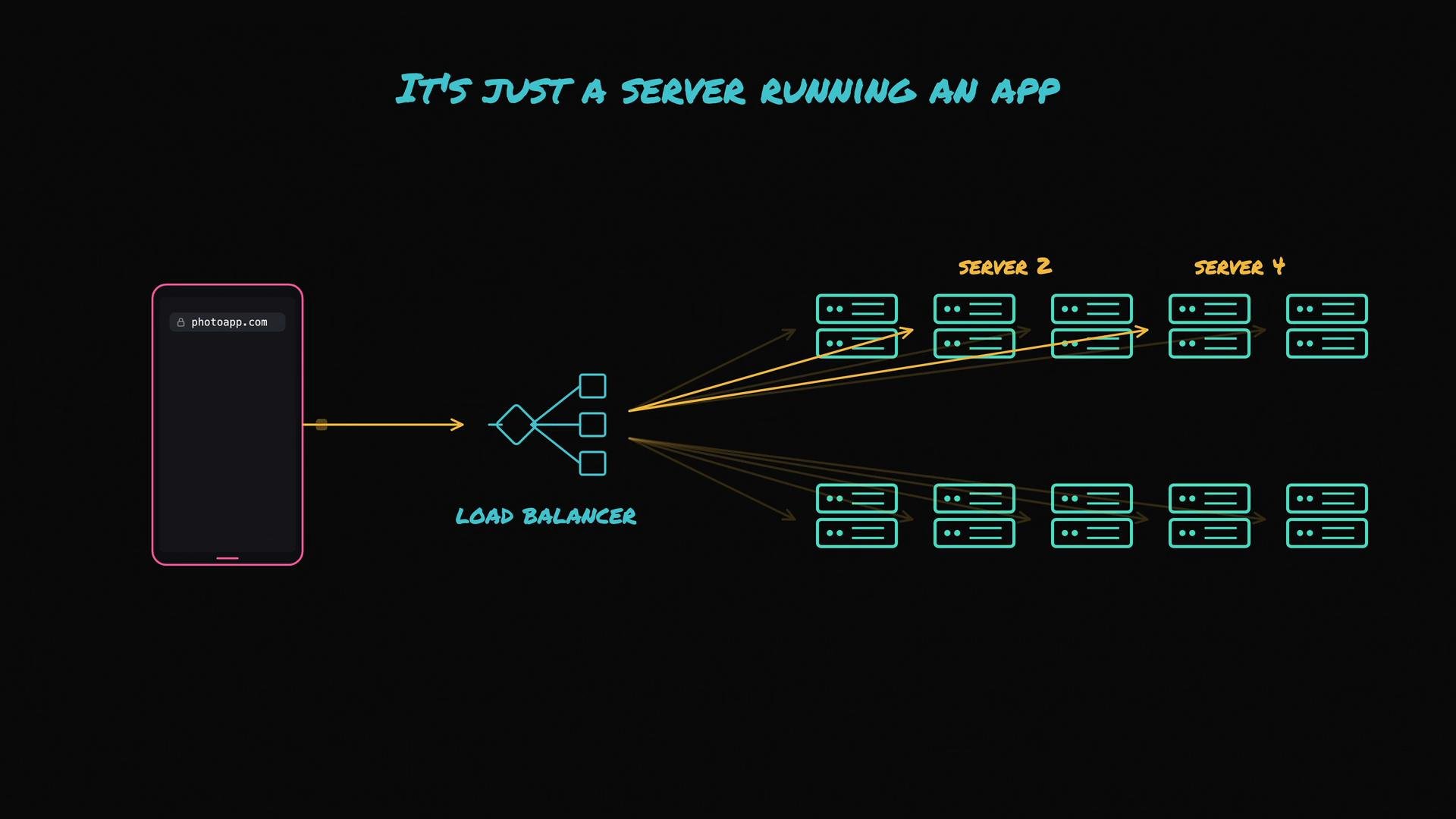
The request lands at the load balancer first. A common misconception is that a load balancer is special hardware — in practice it’s often just a server running software whose job is to accept incoming requests and forward each request to one of the app servers. It may forward one request to server 2, the next to server 4, and so on, distributing traffic across the fleet.
The image depicts a network diagram with a mobile device accessing a site through a load balancer, distributing the request load across multiple servers. It emphasizes the concept with the phrase "It's just a server running an app."
A load balancer is a form of reverse proxy: it accepts client requests on behalf of backend servers and forwards those requests. When you hear “reverse proxy,” picture the load balancer routing traffic to healthy backend app instances.
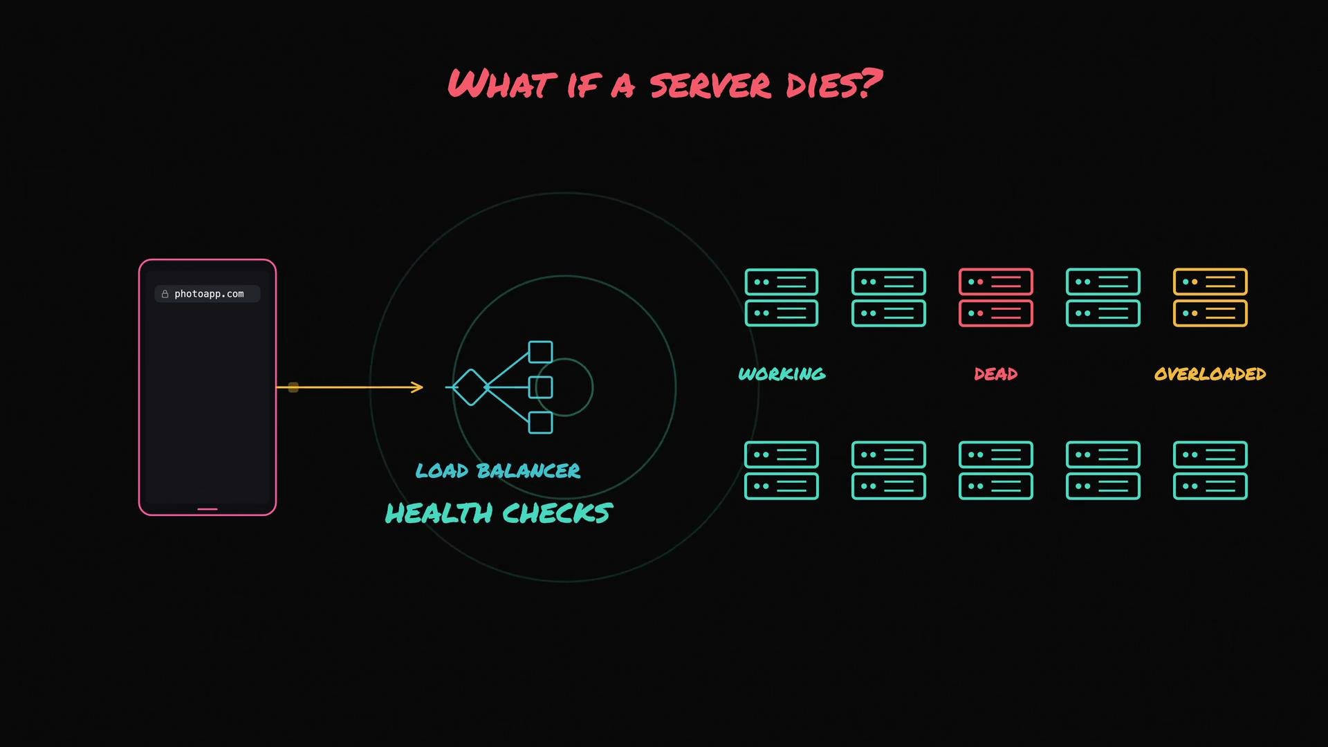
Ideally, traffic is balanced so no single server becomes a bottleneck. If you have ten servers and 100 incoming requests, a well-configured load balancer will aim to spread ~10 requests per server. But what happens if one app server dies? The load balancer must avoid routing traffic to failed backends — that’s why most load balancers perform health checks.
The image illustrates a diagram of a load balancing system managing server status, with categories labeled as working, dead, and overloaded. It demonstrates how requests are distributed and health checks are performed.
Health checks are periodic probes (TCP pings or HTTP requests to a /health endpoint). If server 3 stops responding, the load balancer marks it unhealthy and removes it from rotation. The remaining servers pick up the extra traffic and users typically do not notice dropped requests. Request path (summary):
  • Client asks DNS for photoapp.com.
  • DNS returns the load balancer’s IP.
  • The load balancer selects a healthy backend server.
  • The selected server handles the request (DB access, computing, etc.).
  • The response returns through the load balancer to the client.
How the load balancer chooses backends
  • Round robin: cycles through servers sequentially (1, 2, 3, 1, …). Simple and effective for uniform workloads.
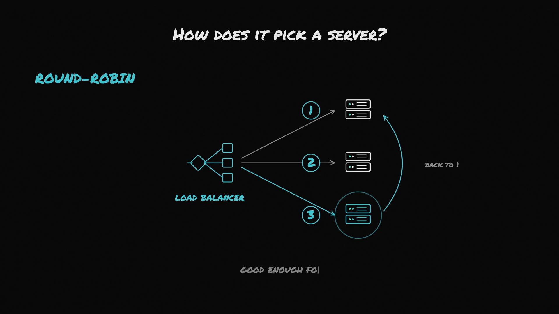
The image illustrates how a load balancer picks a server using the round-robin method, showing a sequential flow of requests distributed among three servers.
  • Least-connections: routes the next request to the server with the fewest active connections. Useful when requests have wide variance in duration; the balancer maintains counters of open connections per backend.
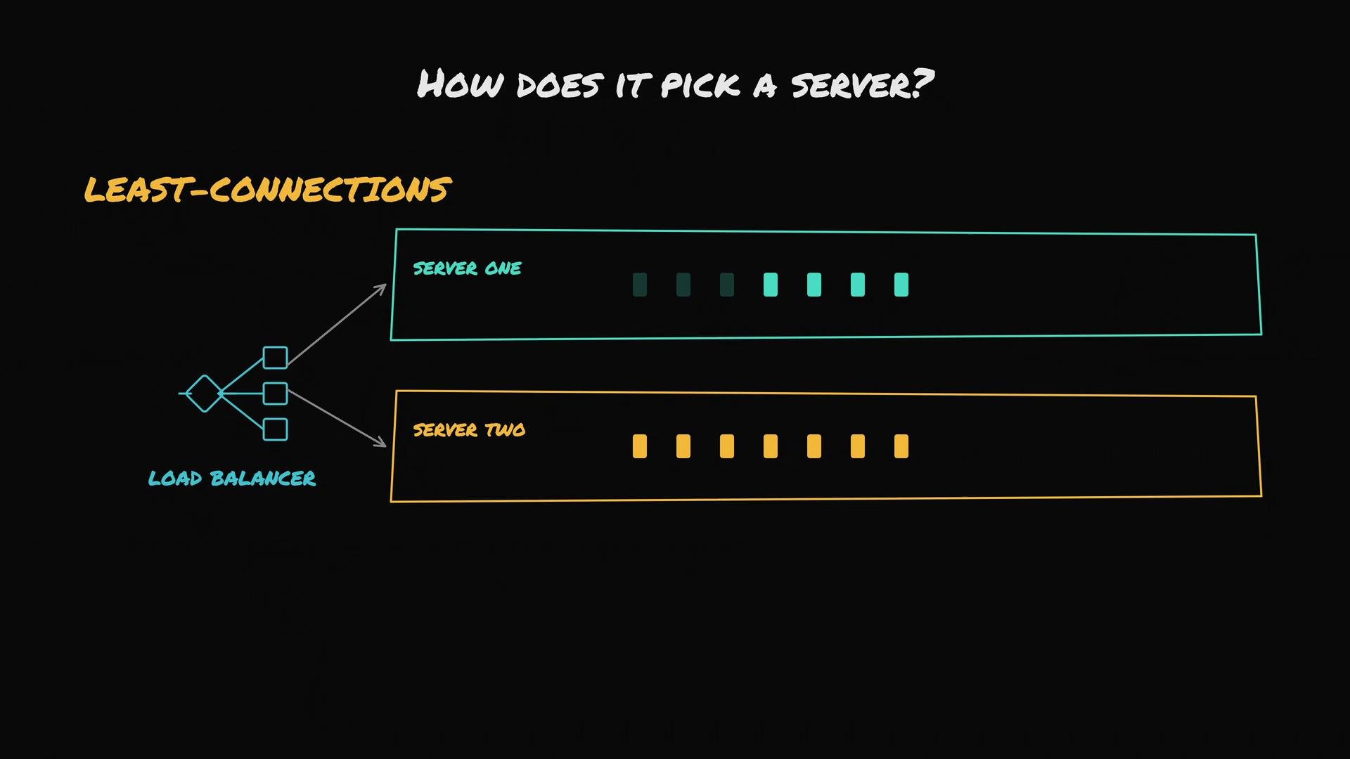
The image illustrates a load balancing concept called "Least-Connections," showing a load balancer directing traffic to two servers based on their current connections. Server One has more connections than Server Two.
  • Weighted distribution: assign higher weights to more powerful servers so they receive proportionally more requests.
Quick comparison Most teams don’t implement load balancers from scratch. Common open-source reverse proxies such as NGINX and HAProxy run on machines you manage. Cloud providers offer managed options like AWS Elastic Load Balancing, which simplify operations and handle many edge cases.

The image compares three tools: NGINX and HAProxy, where you manage the service, and AWS Elastic Load Balancing, which is cloud-managed.
A single load balancer can become a single point of failure: if it dies, all backends become unreachable. Production systems use multiple load balancers for redundancy.
To eliminate that single point of failure, run multiple load balancers. Coordination options include active-passive failover, anycast IPs, virtual IPs with tools like keepalived, or cloud-managed multi-AZ load balancing. How you implement failover depends on your infrastructure and availability requirements.
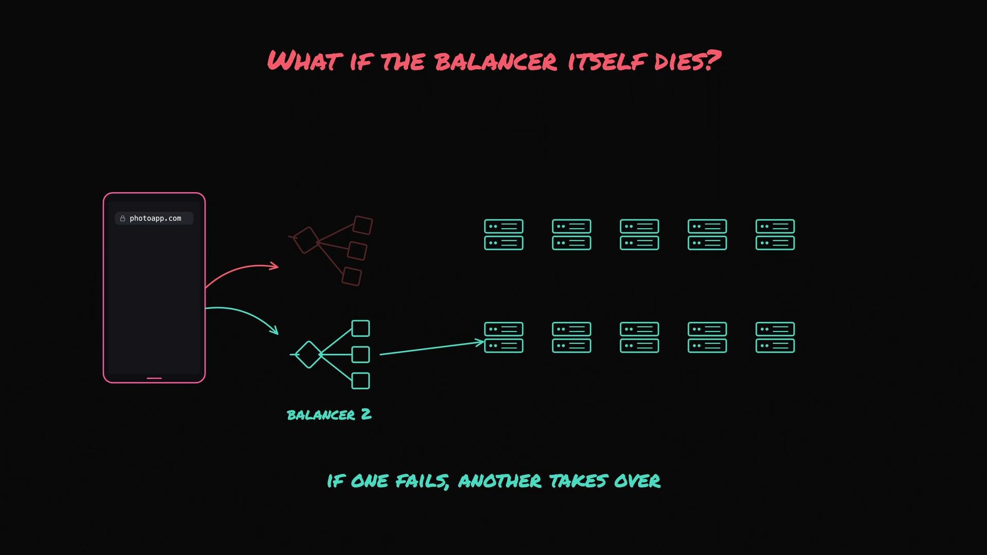
The image is a diagram illustrating a network setup with redundancy, showing two load balancers directing traffic to servers, with a mechanism for handling balancer failure. The text highlights the importance of having a backup if one load balancer fails.
Further reading and references

Watch Video