- Conceptual overview
- Reference topologies (cloud & on-premises)
- Networking requirements
Performance vs. DR Replication
Vault replication modes at a glance:| Mode | Use Case | What Replicates | Promotion Behavior |
|---|---|---|---|
| Performance | Scale reads, reduce latency in local sites | Data (secrets, configs) | N/A |
| Disaster Recovery | Failover with token and lease preservation | Data + Tokens (from any cluster tier) | DR replica becomes new primary on promotion |
- Tokens created on a primary or performance cluster replicate only to their DR cluster.
- Performance secondaries never receive tokens directly from the primary.
- Promoting a DR cluster restores all tokens and leases for uninterrupted operation.
Example: Two Data Centers
Imagine two sites, A and B, each with primary, performance, and DR replicas:- Primary in Data Center A
- Performance Replica in Data Center B
- DR Replica for Primary in Data Center A
- DR Replica for Performance in Data Center B
- Clients in A → Primary; Clients in B → Performance Replica
- Primary → Performance Replica (data only)
- Primary & Performance → their DR clusters (data + tokens)
- On outage, promote the corresponding DR to restore service
AWS Regional Replication
A common AWS pattern spans two regions, each with local DR: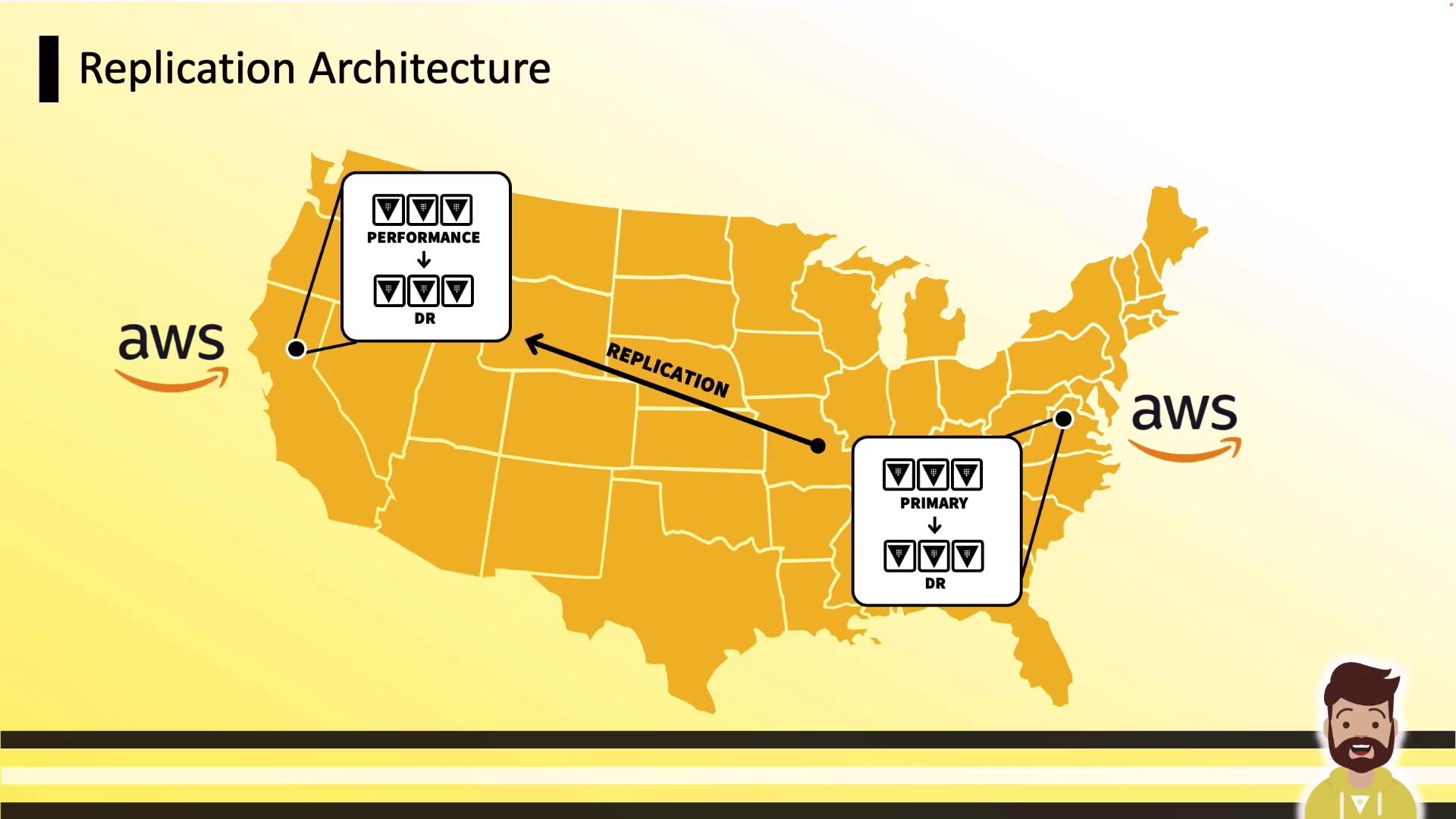
- us-east-1: Primary + DR
- us-west-1: Performance Replica + DR
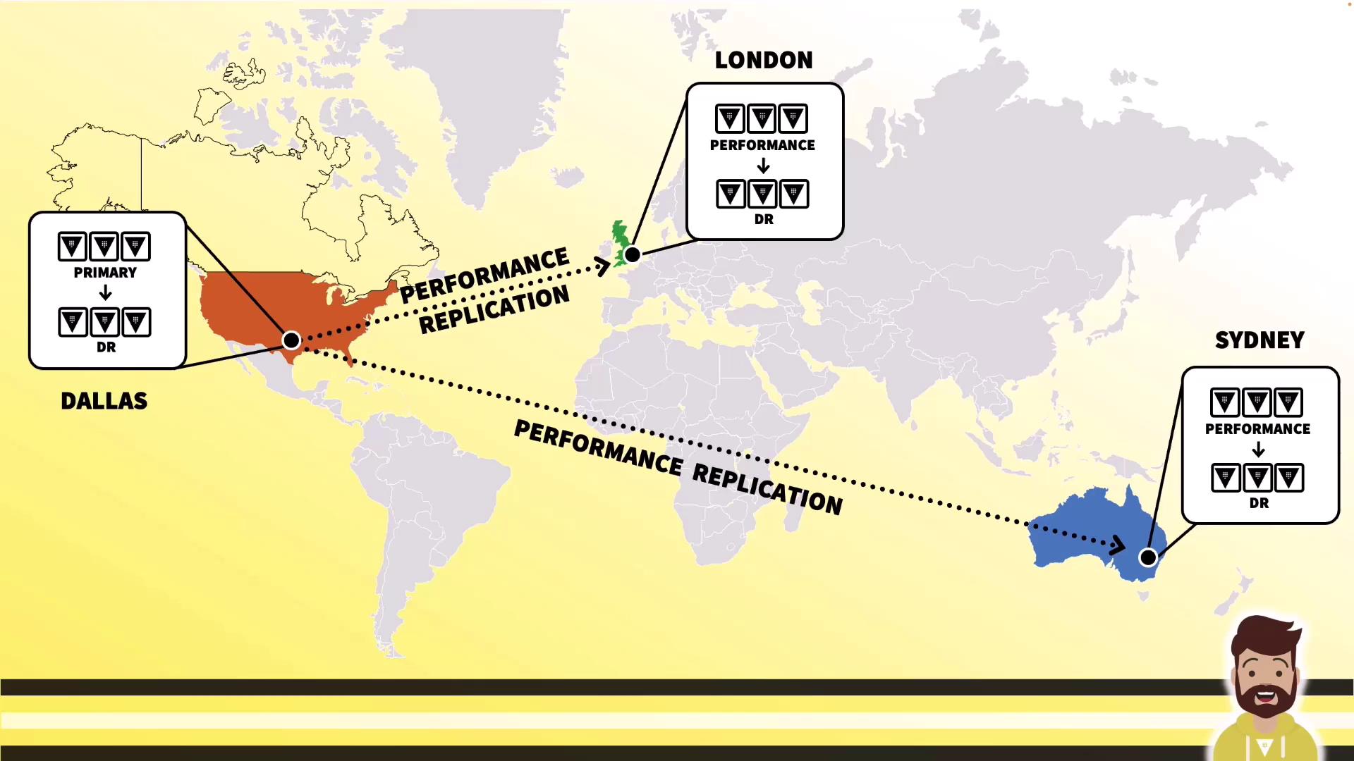
Global Deployment
For global scale, replicate from one primary to multiple regions, each with its own DR: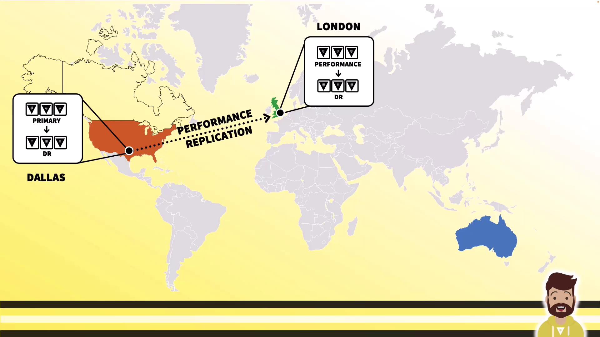
Real-World On-Premises Examples
Customer A: VMware Active-Active
High-availability with VMware clusters across two data centers: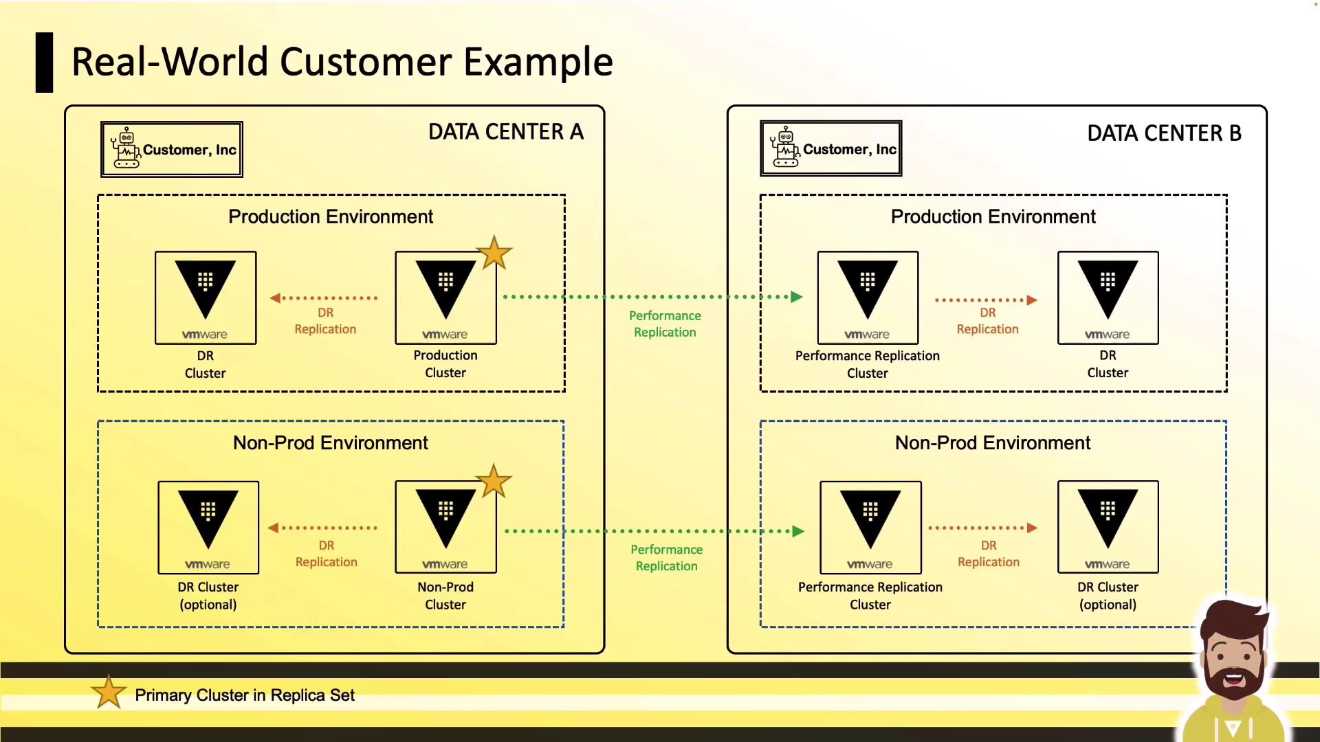
- Production DC A: Primary + DR
- Production DC B: Performance Replica + DR
- Non-Prod: QA and sandbox mirrors for testing
Customer B: On-Premises to AWS
Hybrid topology connecting on-premises primary to AWS: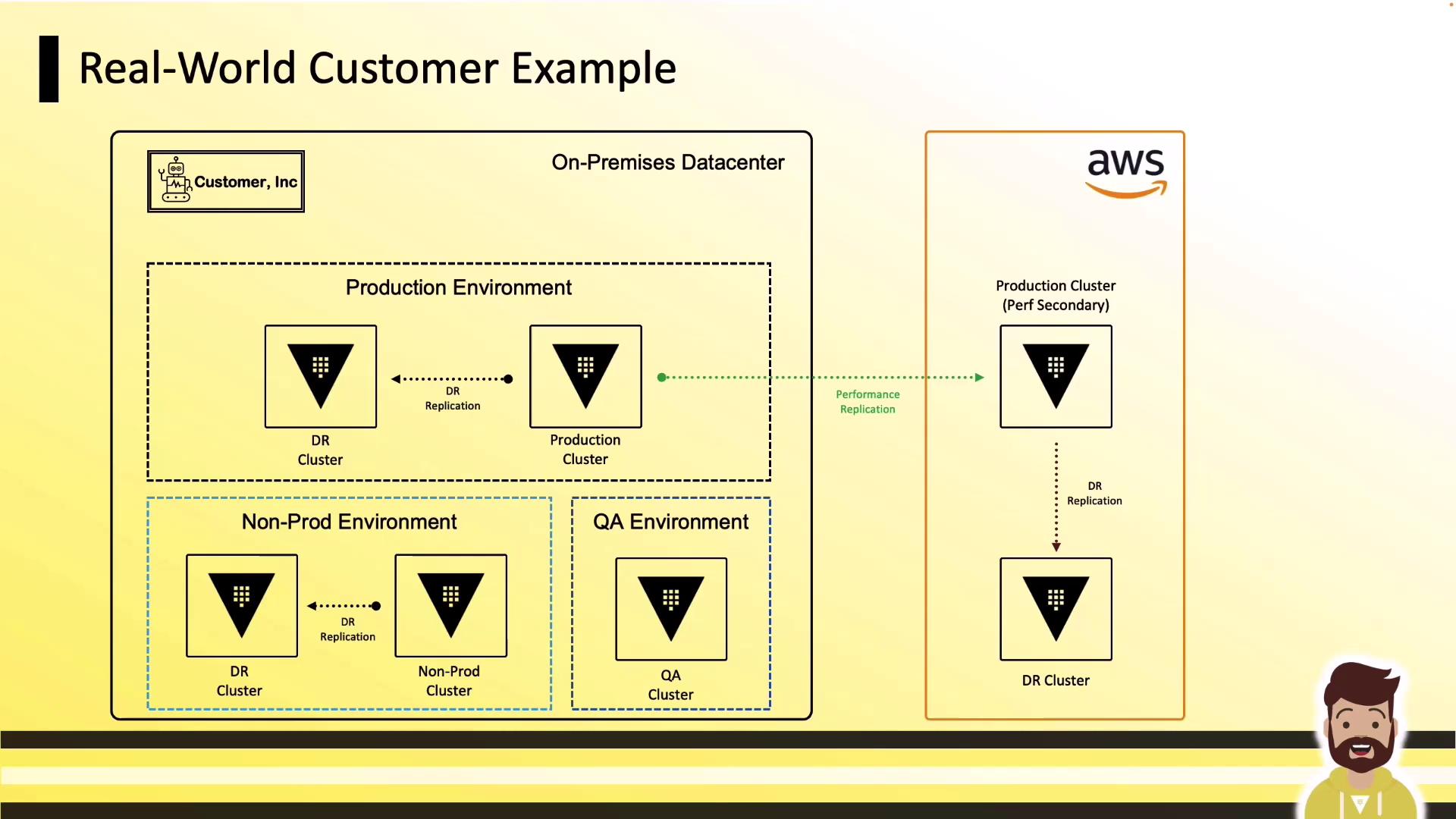
- On-Prem Production: Primary + DR
- AWS: Performance Replica + DR
- Non-Prod & QA: Separate clusters for dev and testing
Networking Requirements
Replicating Vault clusters requires simple connectivity and DNS resolution: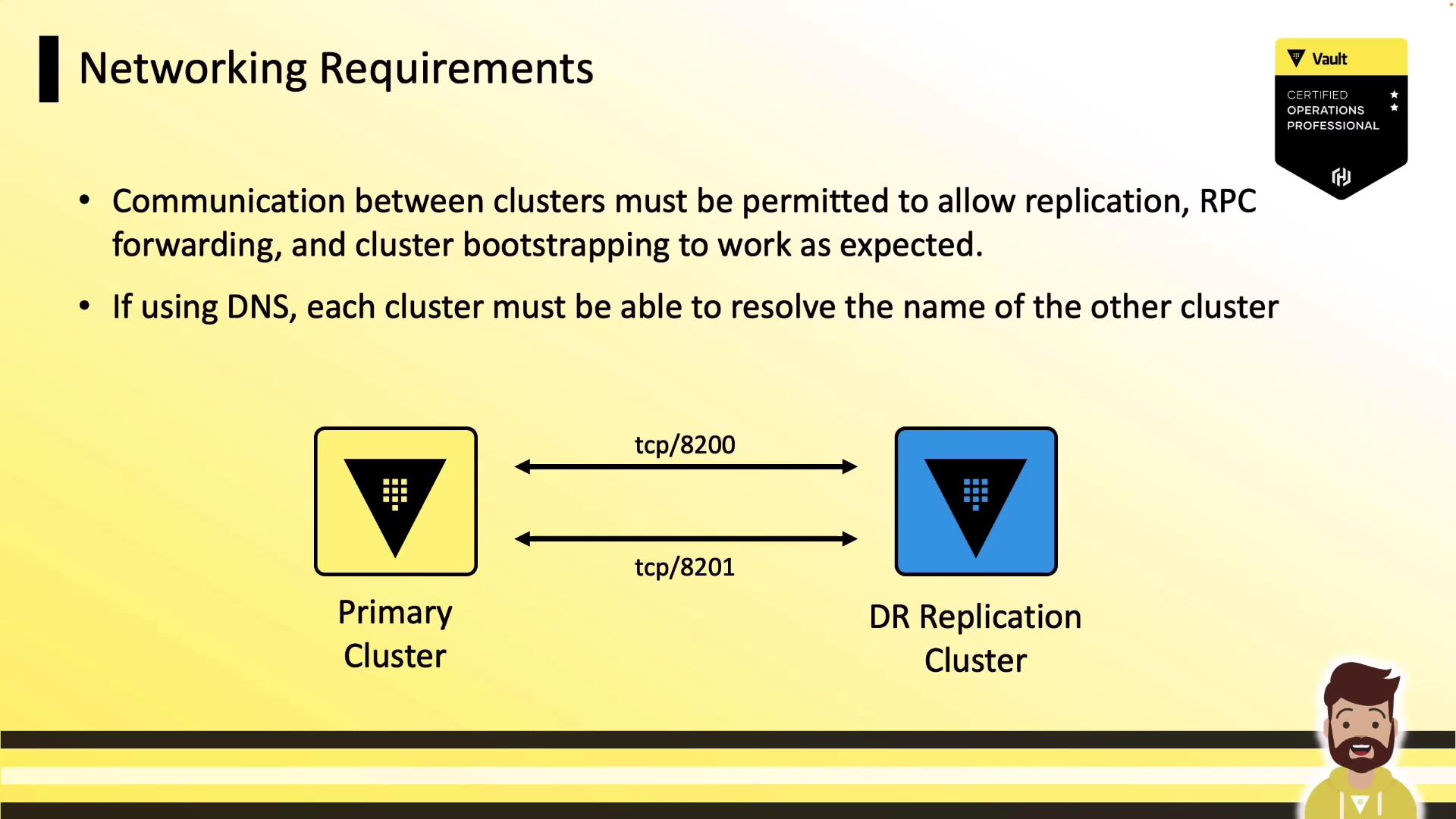
- Open TCP 8200 and 8201 bi-directionally between clusters.
- Restrict access using firewalls or security groups.
- Ensure each cluster can resolve its peers’ DNS names.
Port Reference
| Source | Destination | Port | Protocol | Direction | Purpose |
|---|---|---|---|---|---|
| Vault → Vault (bootstrapping) | Peer Vault clusters | 8200 | TCP | Bi-directional | Cluster bootstrap |
| Vault → Vault (replication) | Peer Vault clusters | 8201 | TCP | Bi-directional | Data & RPC forwarding |
| Client → Load Balancer | Vault API endpoint | 8200 | TCP | Inbound | Client operations |
| Load Balancer → Vault | Vault API servers | 8200 | TCP | Internal | Load balanced traffic |
| Vault → External Services | Database secrets engines, etc. | varies | TCP | Outbound | Secrets engine access |