This guide demonstrates how to configure an egress gateway in a Cilium-enabled Kubernetes cluster and how to inspect traffic flows before and after enabling it. You’ll see how pods are SNAT’d by default, how to enforce egress via a chosen node, and how Cilium forwards traffic (often using VXLAN encapsulation) to the egress node. What we’ll demonstrate
  • Default behavior: pod egress is SNAT’d to the node IP.
  • Enabling Cilium egress gateway and applying a CiliumEgressGatewayPolicy.
  • Capturing traffic to confirm egress from a single gateway node and inspecting VXLAN encapsulation.
Environment overview
ComponentDescription
Cluster3 nodes: 1 control-plane, 2 workers
NetworkingEach node attached to a router on a separate subnet; router used for packet captures
Cilium featureskube-proxy replacement enabled, eBPF masquerade enabled, Cilium version with egress gateway support (v1.17+)
Prerequisites: Cilium must be installed with kube-proxy replacement enabled (kubeProxyReplacement), eBPF masquerade (bpf.masquerade) turned on, and a Cilium release that supports the egress gateway feature. Confirm your cluster networking and node labeling permissions before proceeding.
Cluster pod listing (example)
user1@control-plane:~$ kubectl get pod -o wide
NAME                       READY  STATUS   RESTARTS  AGE    IP           NODE     NOMINATED NODE   READINESS GATES
app1-75c78488c4-d9xw8      1/1    Running  0         3h54s  10.0.2.182   worker2  <none>           <none>
app1-75c78488c4-dbf66      1/1    Running  0         3h54s  10.0.2.126   worker2  <none>           <none>
app1-75c78488c4-dq2dw      1/1    Running  0         3h54s  10.0.1.40    worker1  <none>           <none>
app1-75c78488c4-g521f      1/1    Running  0         3h54s  10.0.1.234   worker1  <none>           <none>
...
user1@control-plane:~$
Verify outbound connectivity from a pod (example)
user1@control-plane:~$ kubectl exec -it app1-75c78488c4-dq2dw -- bash
app1-75c78488c4-dq2dw:~# ping -c 3 8.8.8.8
PING 8.8.8.8 (8.8.8.8) 56(84) bytes of data.
64 bytes from 8.8.8.8: icmp_seq=1 ttl=125 time=16.7 ms
64 bytes from 8.8.8.8: icmp_seq=2 ttl=125 time=15.5 ms
64 bytes from 8.8.8.8: icmp_seq=3 ttl=125 time=15.9 ms

--- 8.8.8.8 ping statistics ---
3 packets transmitted, 3 received, 0% packet loss
rtt min/avg/max/mdev = 15.495/16.039/16.739/0.519 ms
app1-75c78488c4-dq2dw:~# exit
Default behavior (no egress gateway)
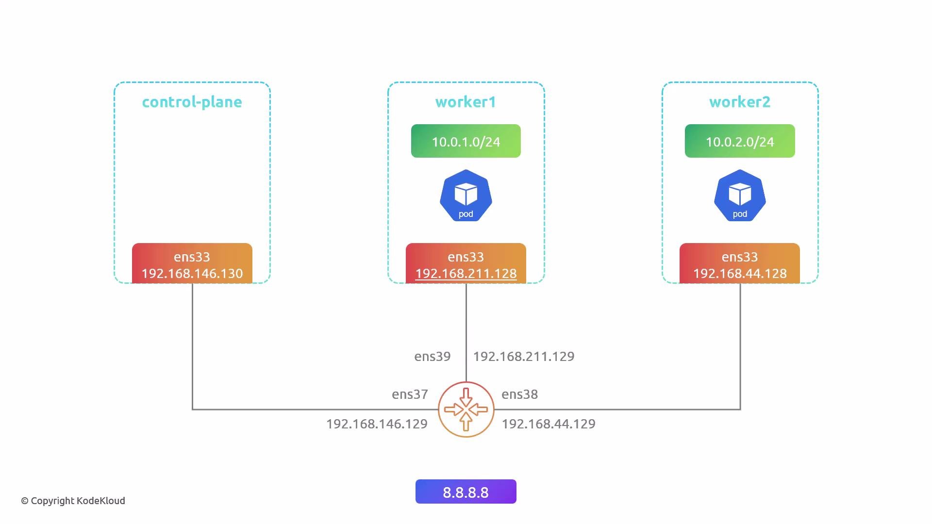
  • Flow: pod IP → node → router → internet. The node performs SNAT, so the router and external services see the node IP as the source address, not the pod IP.
  • If pods run on multiple worker nodes, external services observe different source IPs depending on the node used.
Example router tcpdump showing node IP as source
user1@router:~$ sudo tcpdump -i ens39 -nnv host 8.8.8.8
tcpdump: listening on ens39, link-type EN10MB (Ethernet), snapshot length 262144 bytes
02:09:23.781495 IP (tos 0x0, ttl 62, id 49799, offset 0, flags [DF], proto ICMP (1), length 84)
    192.168.211.128 > 8.8.8.8: ICMP echo request, id 2, seq 16, length 64
02:09:23.798489 IP (tos 0x0, ttl 127, id 62091, offset 0, flags [none], proto ICMP (1), length 84)
    8.8.8.8 > 192.168.211.128: ICMP echo reply, id 2, seq 16, length 64
...
Node interface example (worker1)
user1@worker1:~$ ip addr show ens33
2: ens33: <BROADCAST,MULTICAST,UP,LOWER_UP> mtu 1500 qdisc fq_codel state UP group default qlen 1000
    link/ether 00:0c:29:a4:4a:15 brd ff:ff:ff:ff:ff:ff
    inet 192.168.211.128/24 brd 192.168.211.255 scope global ens33
        valid_lft forever preferred_lft forever
Explanation diagram:
A simple Kubernetes network diagram showing a control-plane and two worker nodes, each with an ens33 interface IP and a pod CIDR (worker1: 10.0.1.0/24, worker2: 10.0.2.0/24), all connected via a central router with additional interface IPs and external DNS 8.8.8.8.
How the egress gateway changes traffic flow
  • Cilium egress gateway centralizes outbound traffic from selected pods through one or more chosen node(s). Those egress node(s) perform SNAT so the external source IP is the chosen egress IP.
  • Internally, Cilium forwards traffic from source nodes to the egress gateway node. In overlay networks (common with Cilium), this forwarding is encapsulated (VXLAN or similar). The egress node decapsulates, performs SNAT, and sends traffic to the internet.
Enable required Cilium options
  1. kube-proxy replacement (ensure kubeProxyReplacement is enabled in values):
kubeProxyReplacement: "true"
  1. eBPF masquerade (native BPF SNAT):
bpf:
  masquerade: true
  1. Enable egress gateway support (depends on Cilium version and values layout). After editing Helm values, upgrade and restart Cilium:
# Upgrade helm release (example)
helm upgrade cilium cilium/cilium --namespace kube-system -f cilium-values.yaml

# Restart Cilium operator and agent
kubectl rollout restart deployment/cilium-operator -n kube-system
kubectl rollout restart daemonset/cilium -n kube-system
Create and apply a CiliumEgressGatewayPolicy
  • Label the node(s) you want to act as egress gateway(s) and reference that label in the policy nodeSelector.
  • Note: label values in YAML matchLabels must be strings. Quote boolean-like values (e.g., “true”).
Label the chosen node (example)
user1@control-plane:~$ kubectl label node worker2 egress=true
node/worker2 labeled
Confirm the label
user1@control-plane:~$ kubectl get node --show-labels
NAME            STATUS   ROLES           AGE   VERSION   LABELS
control-plane   Ready    control-plane   37d   v1.32.3   ... 
worker1         Ready    <none>          37d   v1.32.3   ... 
worker2         Ready    <none>          37d   v1.32.3   ... egress=true,...
Example CiliumEgressGatewayPolicy (egress-gateway.yaml)
  • This example selects pods with label app=app1, matches all destinations (0.0.0.0/0), and configures the node labeled egress: “true” to use egress IP 192.168.44.128.
apiVersion: cilium.io/v2
kind: CiliumEgressGatewayPolicy
metadata:
  name: egress-example
spec:
  selectors:
  - podSelector:
      matchLabels:
        app: app1
    destinationCIDRs:
    - "0.0.0.0/0"
  egressGateway:
    nodeSelector:
      matchLabels:
        egress: "true"
    egressIP: 192.168.44.128
Apply the policy
user1@control-plane:~$ kubectl apply -f egress-gateway.yaml
ciliumegressgatewaypolicy.cilium.io/egress-example created
When authoring CiliumEgressGatewayPolicy YAML, always quote label values (for example: egress: “true”) so they are treated as strings. Also ensure your Cilium version supports the egress gateway feature and that kubeProxyReplacement and bpf.masquerade are enabled.
Verify Cilium BPF egress entries
  • Check the BPF egress table from a Cilium agent pod to confirm source pods are mapped to the configured egress IP:
user1@control-plane:~$ kubectl -n kube-system exec ds/cilium -- cilium-dbg bpf egress list
Defaulted container "cilium-agent" out of: cilium-agent, config (init), mount-cgroup (init), apply-sysctl-overwrites (init), mount-bpf-fs (init), clean-cilium-state (init), install-cni-binaries (init)
Source IP    Destination CIDR    Egress IP         Gateway IP
10.0.1.40    0.0.0.0/0           192.168.44.128    192.168.44.128
10.0.1.126   0.0.0.0/0           192.168.44.128    192.168.44.128
10.0.1.206   0.0.0.0/0           192.168.44.128    192.168.44.128
10.0.1.234   0.0.0.0/0           192.168.44.128    192.168.44.128
10.0.2.110   0.0.0.0/0           192.168.44.128    192.168.44.128
10.0.2.126   0.0.0.0/0           192.168.44.128    192.168.44.128
10.0.2.174   0.0.0.0/0           192.168.44.128    192.168.44.128
10.0.2.182   0.0.0.0/0           192.168.44.128    192.168.44.128
Confirm behavior with packet capture
  • Start a capture on your router. To write a pcap file and capture ICMP on all interfaces:
# Capture ICMP on all interfaces and write to file
user1@router:~$ sudo tcpdump -i any icmp -w egress-demo.pcap
# Or preview in terminal on a single interface for a host
user1@router:~$ sudo tcpdump -i ens39 -nnv host 8.8.8.8
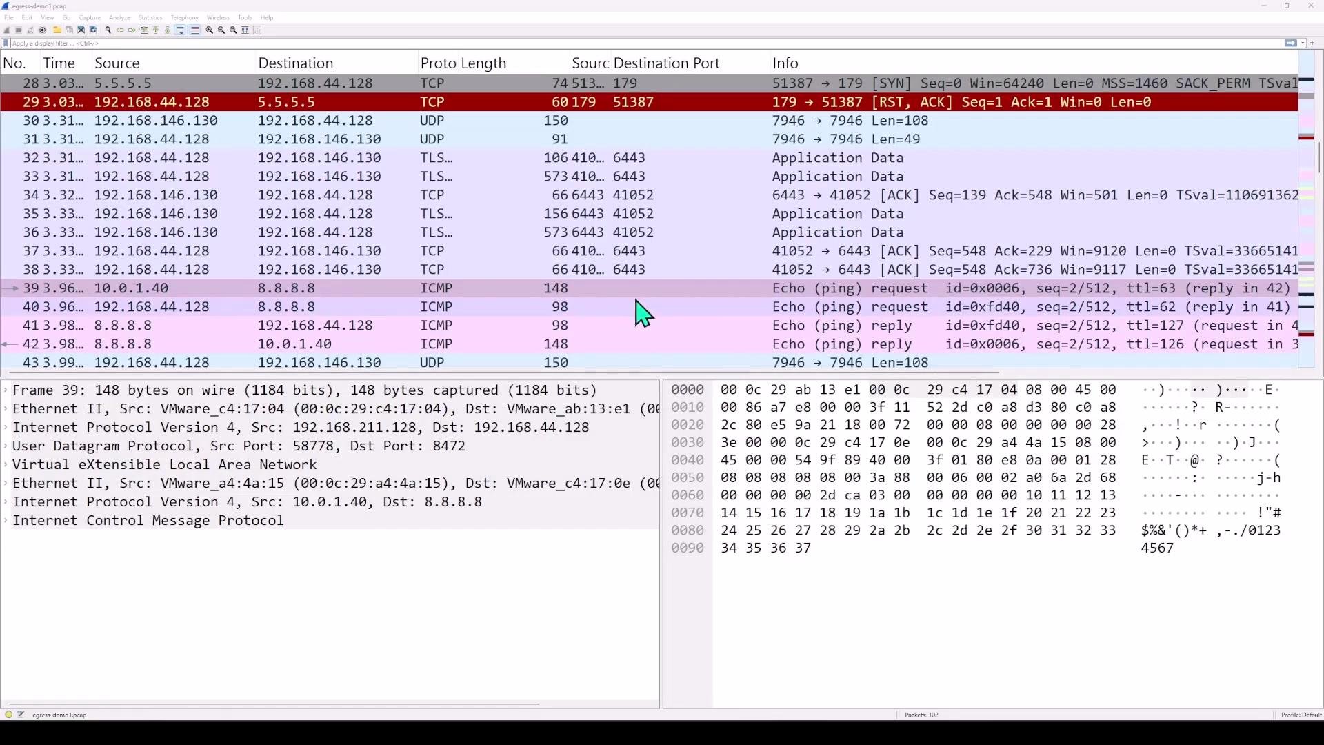
  • From a pod on worker1 (not the egress gateway), ping 8.8.8.8 and stop the capture after a few packets:
user1@control-plane:~$ kubectl exec -it app1-75c78488c4-dq2dw -- bash
app1-75c78488c4-dq2dw:~# ping -c 4 8.8.8.8
...
Expected router capture after enabling egress gateway
  • Router should now see the configured egress IP (192.168.44.128) as the source for traffic from pods matched by the policy instead of the pod’s local node IP.
Example tcpdump showing traffic egressing from the egress node (worker2/egress IP)
user1@router:~$ sudo tcpdump -i ens38 -nnv host 8.8.8.8
tcpdump: listening on ens38, link-type EN10MB (Ethernet), snapshot length 262144 bytes
05:28:32.380252 IP (tos 0x0, ttl 62, id 49930, offset 0, flags [DF], proto ICMP (1), length 84)
    192.168.44.128 > 8.8.8.8: ICMP echo request, id 3, seq 18, length 64
05:28:32.394744 IP (tos 0x0, ttl 127, id 3447, offset 0, flags [none], proto ICMP (1), length 84)
    8.8.8.8 > 192.168.44.128: ICMP echo reply, id 3, seq 18, length 64
...
Inspecting the packets (VXLAN encapsulation)
  • When the source pod is on a different node than the configured egress node, Cilium forwards the packet across nodes using overlay encapsulation (often VXLAN). The outer header shows node→egress-node (physical IPs) and the inner payload contains the original pod→internet packet. The egress node decapsulates, SNATs to the egress IP, and sends the packet to the internet. Replies are received by the egress node and forwarded/decapsulated back to the source node as needed.
Wireshark view example:
A Wireshark packet-capture window showing a list of network packets (TCP, UDP, ICMP, TLS) with columns for source/destination, ports, and info. The lower panes display the selected packet's protocol details and hex/ASCII dump.
Representative Wireshark decoded summary (illustrative)
Frame 39: ... (VXLAN encapsulated)
Ethernet II, Src: worker1-eth, Dst: worker2-eth
Internet Protocol Version 4, Src: 192.168.211.128, Dst: 192.168.44.128   <-- outer headers (node -> egress-node)
User Datagram Protocol, Src Port: 58778, Dst Port: 8472
Virtual eXtensible Local Area Network
  Inner Ethernet II, Src: cilium, Dst: cilium
  Internet Protocol Version 4, Src: 10.0.1.40, Dst: 8.8.8.8   <-- inner headers (pod -> internet)
  ICMP Echo (ping) request
Decapsulated packet leaving the egress node:
Frame 40: ...
Ethernet II, Src: worker2-eth, Dst: router
Internet Protocol Version 4, Src: 192.168.44.128, Dst: 8.8.8.8   <-- packet sent to internet with SNAT to egress node IP
ICMP Echo (ping) request
Reply returned and delivered back to the pod (encapsulated back if required):
Frame 42: ... (VXLAN inner packet containing 8.8.8.8 -> 10.0.1.40)
Summary and best practices
  • Default: each node SNATs pod outbound traffic to its node IP; external servers will see multiple source IPs if pods are distributed across nodes.
  • With Cilium egress gateway: you can centralize egress IPs by selecting one or more egress nodes. Matched pod traffic is forwarded (often via VXLAN), SNAT’d at the egress node, and sent to the internet — useful for predictable outbound IPs, firewalling, and auditing.
  • Ensure:
    • kubeProxyReplacement is enabled,
    • eBPF masquerade (bpf.masquerade) is enabled,
    • quoting label values (e.g., egress: “true”) in YAML to avoid boolean parsing issues.
  • For production: consider multiple egress nodes and failover strategies to avoid single points of egress.
Links and references If you’d like, I can also provide:
  • A granular policy example selecting a single destination IP (e.g., “8.8.8.8/32”),
  • Steps to configure multiple egress nodes with failover,
  • Commands to inspect Cilium policy state and logs for troubleshooting.

Watch Video

Practice Lab