Topology overview
Consider a simple two-node cluster where the nodes are on different physical subnets (separated by one or more routers). In this example:- Node 1 physical interface (Ethernet0): 172.16.2.0/24, gateway R1 = 172.16.2.1
- Node 2 physical interface (Ethernet0): 172.16.3.0/24, gateway R2 = 172.16.3.1
- Pod CIDRs assigned by CNI:
- Node 1 pod CIDR: 10.244.1.0/24
- Node 2 pod CIDR: 10.244.2.0/24
- Pod addresses:
- Pod 1 (on Node 1): 10.244.1.1
- Pod 2 (on Node 2): 10.244.2.1
- Encapsulation (tunnel) mode
- Native routing mode
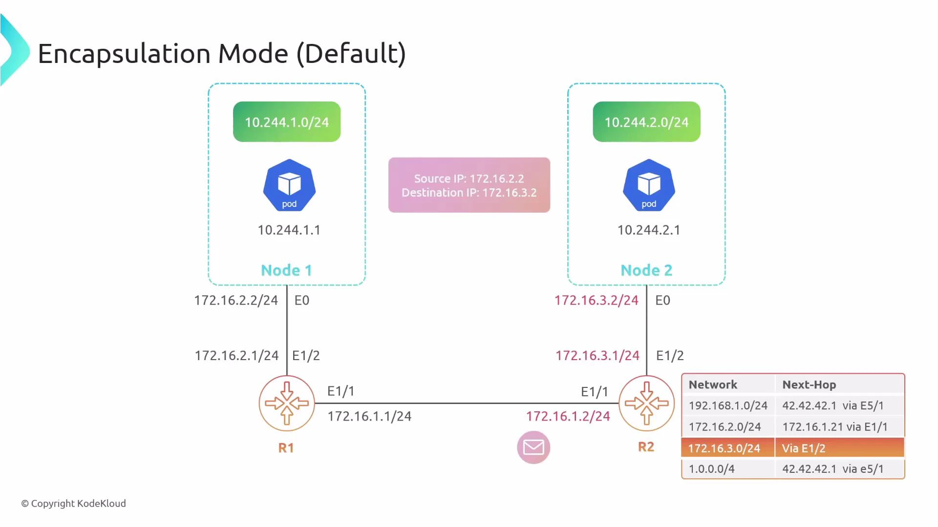
Encapsulation mode (tunnel)
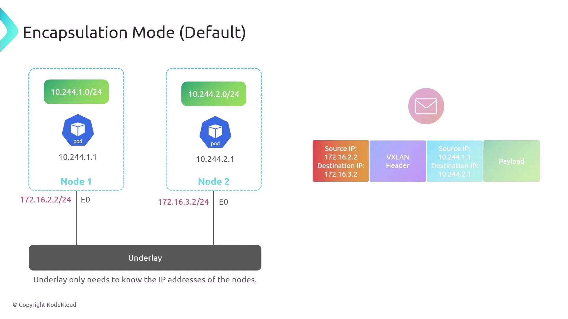
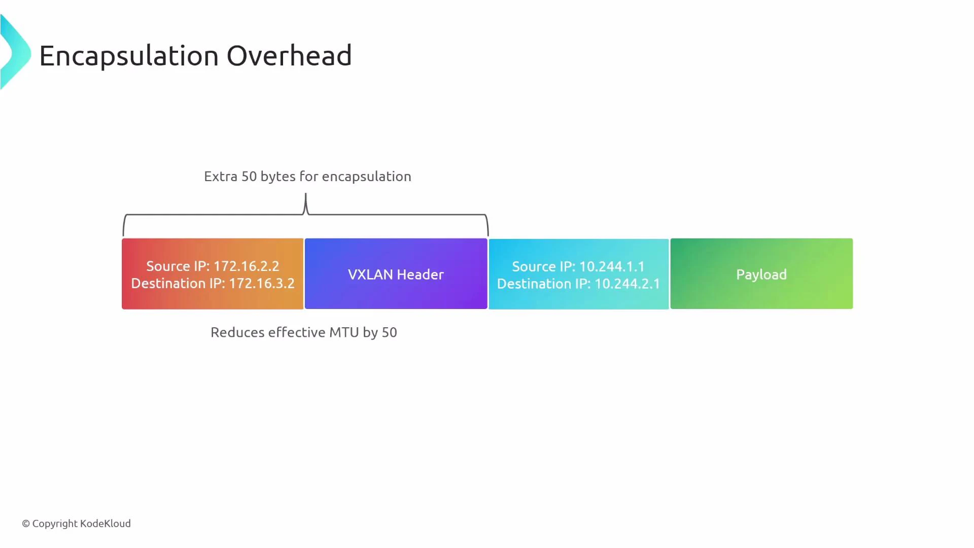
In encapsulation mode, the original pod-originated packet (the inner packet) is wrapped inside an outer packet whose source and destination are the physical node IPs. The underlay only needs to route the outer IPs (the node IPs), not the pod CIDRs.- Inner packet: src=10.244.1.1, dst=10.244.2.1
- Outer packet: src=node1_IP (e.g., 172.16.2.2), dst=node2_IP (e.g., 172.16.3.2)
Encapsulation details
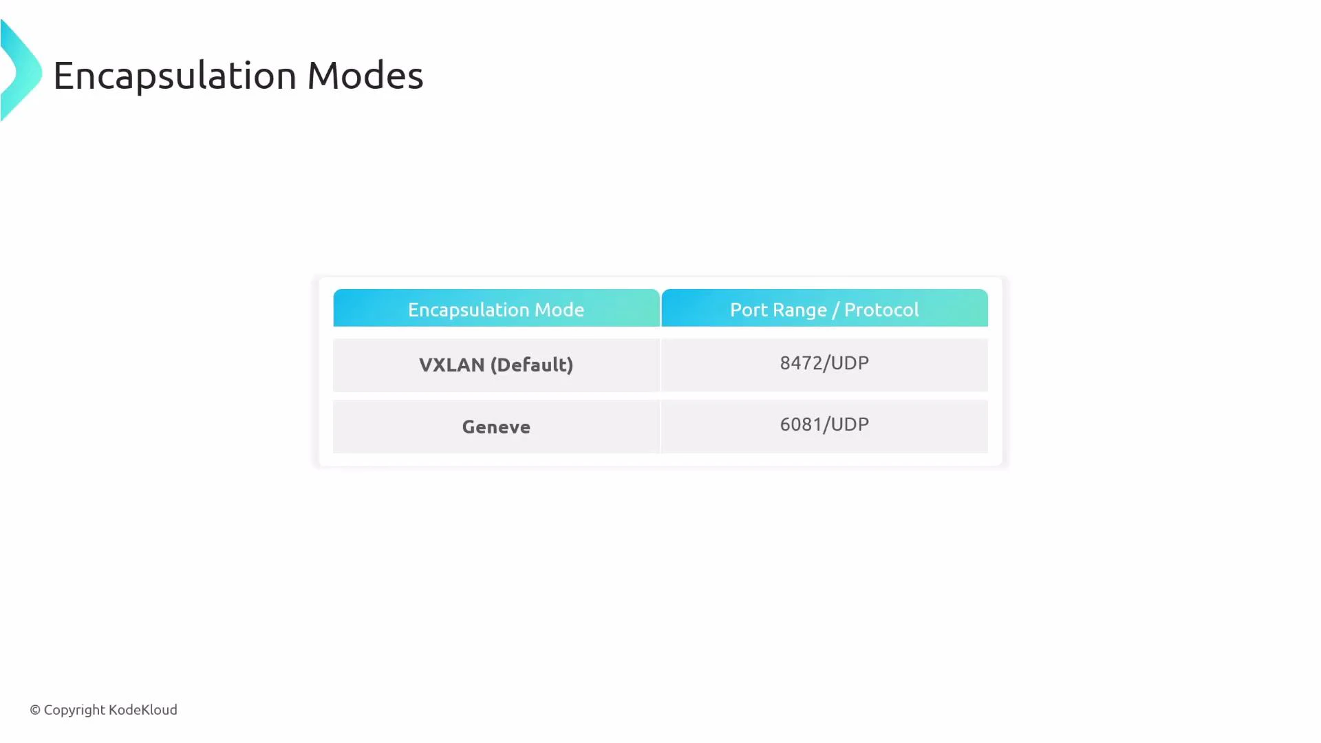
Encapsulation adds a tunnel header and outer IP/UDP/etc. Common tunneling protocols used by CNIs include:- VXLAN (IANA-assigned UDP port 4789; historically some implementations used UDP 8472)
- Geneve (typically UDP port 6081)
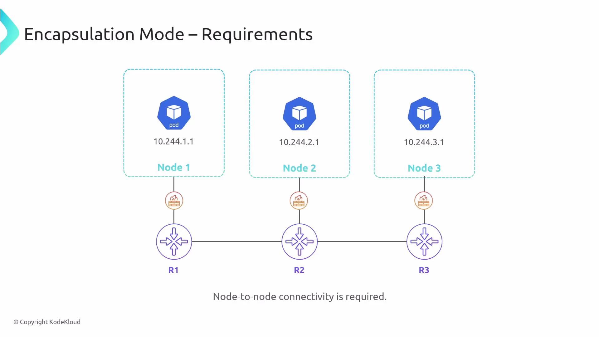
Requirements for encapsulation mode
- Node-to-node IP connectivity: every node IP must be reachable from every other node.
- Firewall and security groups must allow the tunnel/encapsulation protocol (UDP ports used by VXLAN/Geneve, etc.).
- Ensure MTU is sized to account for tunnel overhead (or enable jumbo frames).
Encapsulation protocol options
Overhead and MTU considerations
Encapsulation typically adds ~50 bytes of overhead (outer IP/UDP + tunnel header for VXLAN/Geneve). That reduces the effective MTU for the inner packet and can cause fragmentation. Mitigation strategies:- Reduce the inner MTU on host interfaces (e.g., subtract tunnel overhead).
- Use jumbo frames on the underlay.
- Monitor for fragmentation and adjust accordingly.
Pros and cons of encapsulation
Encapsulation is often simpler to deploy because the physical network only needs to reach node IPs. Ensure firewall rules and MTU settings are adjusted for the chosen tunnel protocol (VXLAN/Geneve).
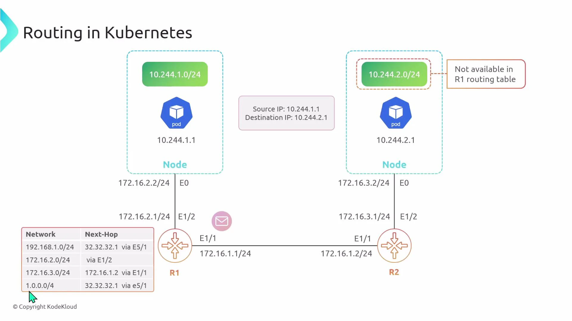
Native routing mode
In native routing mode, pods’ IPs are routed across the physical network without encapsulation. The inner packet travels across the underlay unchanged, so routers must know how to reach each node’s pod CIDRs. If Pod 1 sends to Pod 2, the packet leaves Node 1 with src=10.244.1.1 and dst=10.244.2.1. The physical router R1 must have a route pointing to Node 2’s pod CIDR (10.244.2.0/24) for the packet to be delivered.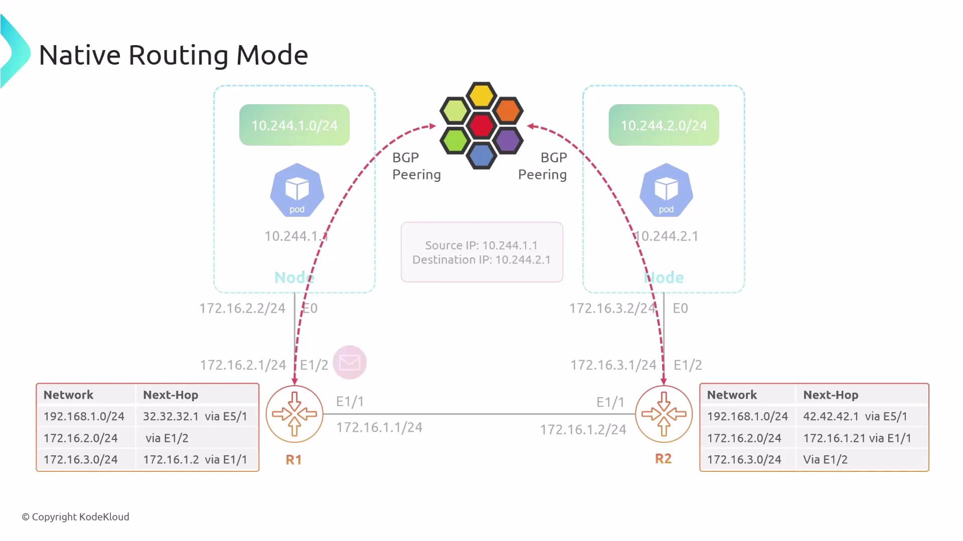
How underlay routing can learn pod CIDRs
To make native routing practical at scale, the underlay must learn pod CIDRs. Common approaches:- Static routes — simple but not scalable or fault-tolerant.
- Dynamic routing (BGP) — Cilium can advertise pod CIDRs into the physical fabric using BGP so routers learn where to forward pod traffic.
- SDN/orchestration solutions that distribute routes to the underlay.
Configuring native routing in Cilium
Cilium defaults to encapsulation. To enable native routing, set the routing mode to “native” and configure which CIDR ranges should be treated as natively routable. This allows you to mix modes: some pod CIDRs can be native while others remain encapsulated. Example Cilium configuration snippet:- ipv4NativeRoutingCIDR defines which IP range(s) Cilium advertises or treats as natively routed.
- Traffic within that CIDR will be forwarded natively by the underlay; traffic outside falls back to encapsulation.
- You can restrict the range (for example, a /17) to mix native and encapsulated traffic across different pod groups.
Pros and cons of native routing
Native routing requires careful underlay configuration. If your physical network lacks routes for the pod CIDRs (or your cloud provider blocks route advertisement), pod-to-pod traffic can be dropped. Plan route distribution (e.g., BGP) before switching to native routing.
Quick comparison
Choosing a mode
- Use encapsulation if you need portability and minimal underlay changes (default for many environments).
- Use native routing for maximum performance and visibility if you can reliably distribute pod routes into the underlay (for example with BGP).
- Consider a hybrid approach: advertise only selected CIDRs natively and encapsulate others.
Links and references
- Cilium documentation — Routing and node connectivity: https://docs.cilium.io/
- Kubernetes networking concepts: https://kubernetes.io/docs/concepts/cluster-administration/networking/
- VXLAN overview: https://tools.ietf.org/html/rfc7348
- Geneve overview: https://tools.ietf.org/html/rfc8926
- BGP basics: https://en.wikipedia.org/wiki/Border_Gateway_Protocol
Summary
- Encapsulation (tunneling) is simpler to deploy and portable, but adds overhead and MTU considerations.
- Native routing removes encapsulation overhead and improves performance but requires route distribution into the physical network (BGP or static routes).
- Cilium supports both modes and allows mixing them by CIDR. Choose based on your underlay capabilities, performance goals, and operational constraints.