

This article simplifies many details for clarity. The exact behaviour may vary with Cilium versions and configuration (for example: kube-proxy replacement, encapsulation mode, or network policy settings).
Node interfaces and pod addressing
Assume a two-node Kubernetes cluster with Cilium installed. On a node (Node1) the relevant host interfaces might look like:
To confirm the node CIDR/allocated pool used by Cilium, inspect the agent debug output:
Services and backends
Create a ClusterIP Service that selects backend pods:High-level eBPF attachments
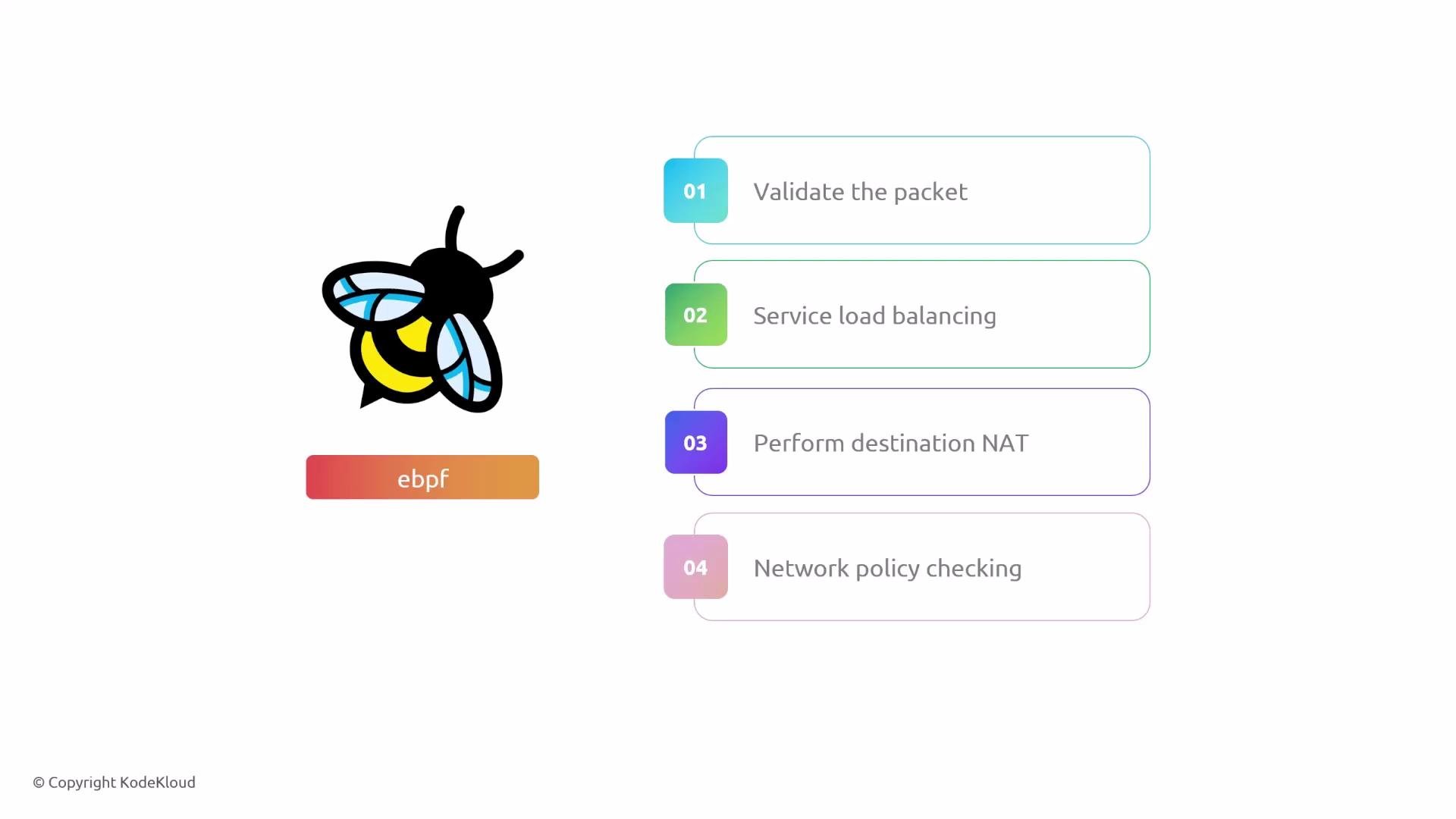
Cilium attaches eBPF programs to multiple interfaces (per-pod veths, host interfaces, VXLAN device, etc.). Inspect currently attached programs with bpftool from within the Cilium agent:- Validate and classify the packet
- Perform service load balancing
- Apply destination NAT (service translation)
- Enforce network policy (accept or drop)
Packet walk: pod-to-pod (same node)
Scenario: frontend pod (10.0.2.172) on Node1 sends to backend service (10.96.71.79:80). Example flow tuple:- sourceIP: 10.0.2.172
- destIP: 10.96.71.79
- sourcePort: ephemeral (e.g., 5578)
- destPort: 80
- The frontend routes via the node gateway (cilium_host 10.0.2.241) — the packet travels over the pod-host veth.
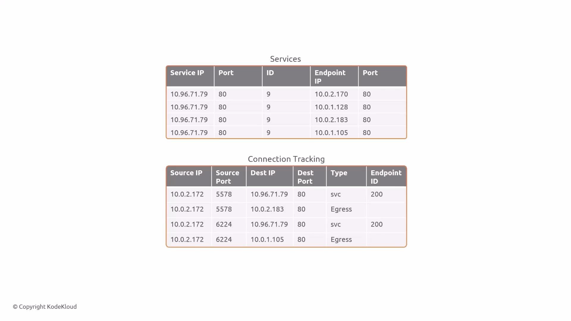
- The eBPF program attached to the pod veth (cil_from_container) runs. It looks up the service and selects a backend endpoint.
- Cilium performs DNAT to the chosen backend pod IP (for example, 10.0.2.183) and creates connection-tracking entries for both directions so that return traffic is correctly translated.
- The eBPF program looks up the destination in the cilium_lxc map to obtain destination MAC and host veth info, then forwards the packet out the matching host veth toward the destination pod.
Packet walk: pod-to-pod (reverse direction)
When the backend (10.0.2.183) responds, tuple values flip:- sourceIP: 10.0.2.183
- destIP: 10.0.2.172
- sourcePort: 80
- destPort: ephemeral (e.g., 5578)
- The backend’s default route sends traffic to its cilium_host (10.0.2.241).
- The pod’s host veth ingress trigger runs (cil_from_container), which checks conntrack for the original flow.
- Conntrack state is used to rewrite addresses back to the service IP if required and to identify the frontend endpoint (for example endpoint ID 3959).
- The eBPF program forwards the packet to the frontend pod’s veth.
Packet walk: pod-to-pod (different nodes)
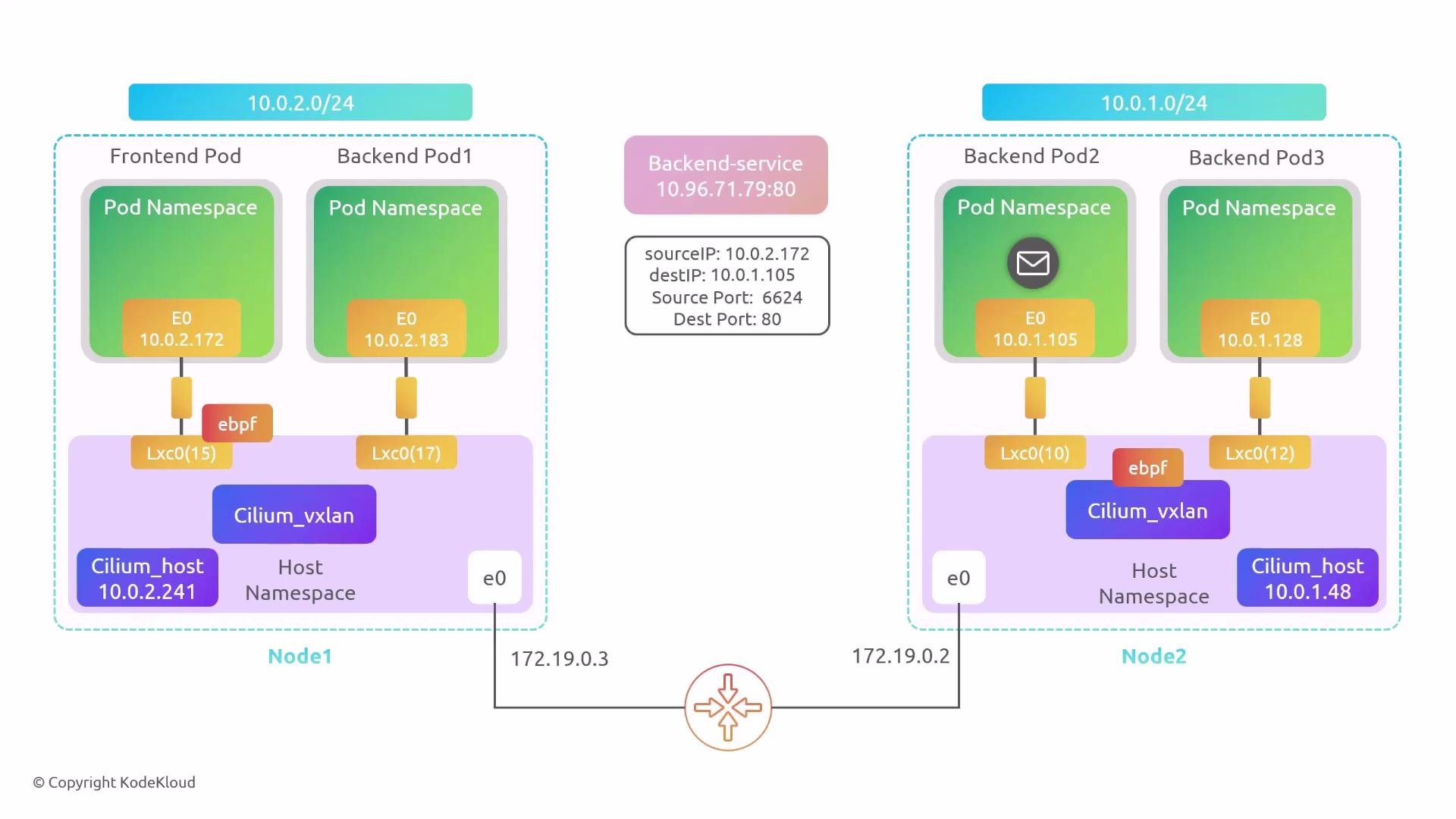
Now consider the frontend (Node1, 10.0.2.172) contacting the service but Cilium selects a backend on Node2 (10.0.1.105). Example initial tuple:- sourceIP: 10.0.2.172
- destIP: 10.96.71.79
- sourcePort: ephemeral
- destPort: 80
- The frontend sends the packet to local cilium_host (10.0.2.241).
- The local eBPF program resolves a backend endpoint (10.0.1.105) that belongs to Node2. Cilium looks up the ipcache (cilium_ipcache) mapping for that pod to obtain the node-level host address (the node’s eth0 IP).
- Example ipcache lookup shows the host IP for Node2 (172.19.0.2):
- Because the backend is remote and the cluster is using VXLAN encapsulation, Cilium encapsulates the packet. The outer packet uses Node1 and Node2 host IPs as the VXLAN outer source/destination and egresses via cilium_vxlan.
- On Node2, the VXLAN decapsulated packet arrives on cilium_vxlan. The eBPF program attached to that device (cil_from_overlay) decapsulates and then performs an inner-packet lookup in cilium_lxc to find the destination MAC and host veth to forward to the pod.
Wrapping up
This lesson summarized the higher-level packet flow when using Cilium with eBPF:- Pods connect to the host via per-pod veth pairs; the per-node cilium_host acts as the pod gateway.
- eBPF programs are attached to many interfaces (pod veths, host, vxlan) and perform packet validation, load balancing, DNAT, and policy enforcement.
- Cilium uses BPF maps (for example cilium_lxc and cilium_ipcache) for fast lookups of MACs, endpoint IDs and node mappings.
- For remote endpoints Cilium encapsulates traffic (VXLAN in this example) using node IPs as outer addresses, decapsulates on the destination node and forwards to the pod.
- Connection tracking carries state for DNAT and reverse translation so services behave as expected.
Conceptual reminder: the ordering of eBPF hooks and specific packet transformations can vary with Cilium configuration (encapsulation vs. direct routing, kube-proxy replacement, etc.), kernel versions and user-space tooling. Use the Cilium debugging tools and bpftool to inspect live behaviour in your environment.
Links and references
- Cilium documentation: https://cilium.io/docs/
- Kubernetes concepts: https://kubernetes.io/docs/concepts/overview/what-is-kubernetes/
- bpftool reference: https://man7.org/linux/man-pages/man8/bpftool.8.html